Section -1 Delta PLC Programming 5 basic Instructions NO, NC, direct Coil, Set Coil and Reset Coil.
Instruction
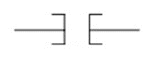
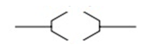
NO Contact
NC Contact
Direct Coil
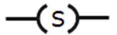
Set Coil
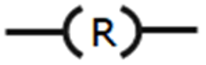
Reset Coil
Used To:
Normally open
Normally closed
Coil driven output
Latch a bit ON
Unlatch a bit OFF
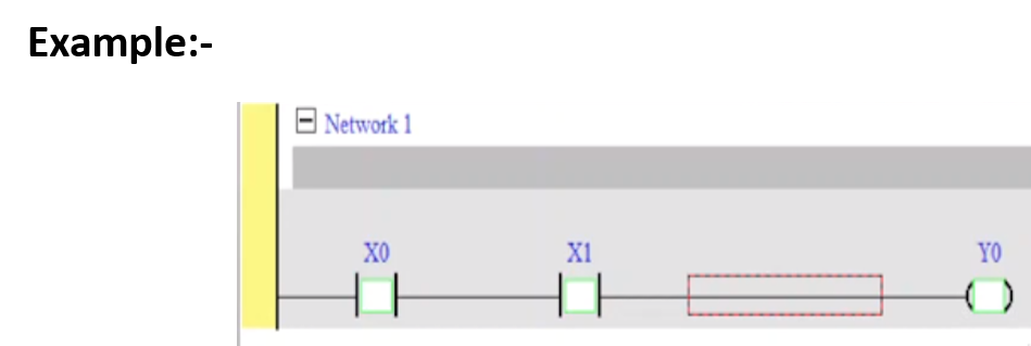
NO Contact
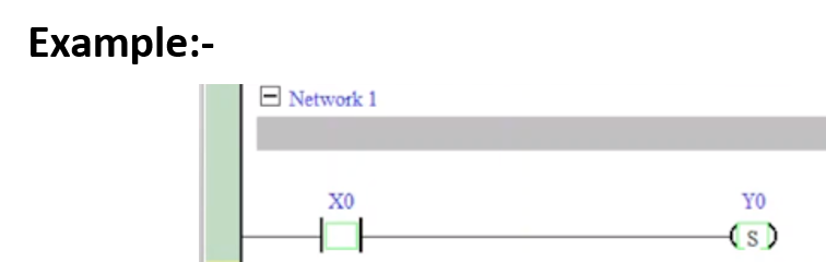
NO Contact : Using a normally open (NO) switch X0 (“A” switch or “A” contact). When X0 is not pressed, the contact will be open loop (Off), so Y0 will be Off. When X0 is pressed, the contact will be On, so Y0 will be On.
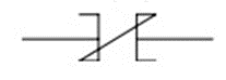
NC Contact.
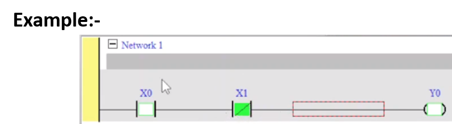
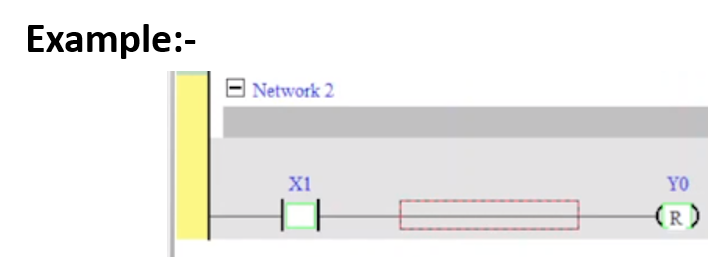
NC Contact :-
Using a normally closed (NC) switch X1 (“B” switch or “B” contact). When X1 is not pressed, the contact will be On, so Y1 will be On. When X1 is pressed, the contact will be open loop (Off), so Y1 will be Off
Direct Coil.
Direct Coil :-
The combination logic of more than one input devices. Output Y2 will be On when X2 is not pressed or X3 and X4 are pressed.
Set Coil.
Set Coil :-
When the SET instruction is driven, its designated device will be “On” and keep being On both when SET instruction is still being driven or not driven. Use RST instruction to set “Off” the device
Reset Coil.
Reset Coil :-
When the RST instruction is driven, the actions of the designated devices are:
Section -2 Timer of Delta DVP PLC using.
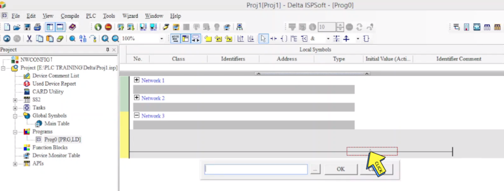
Step 1 :-
Click on “Rung”
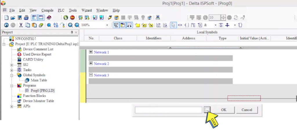
Step 2 :-
Click on “new Tap”
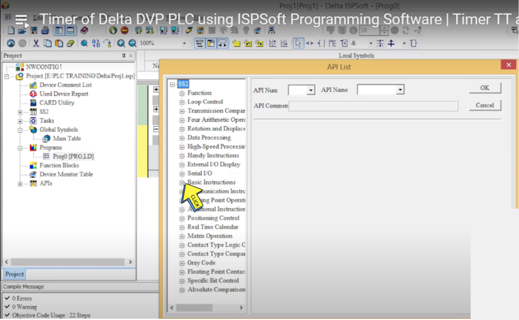
Step 3:-
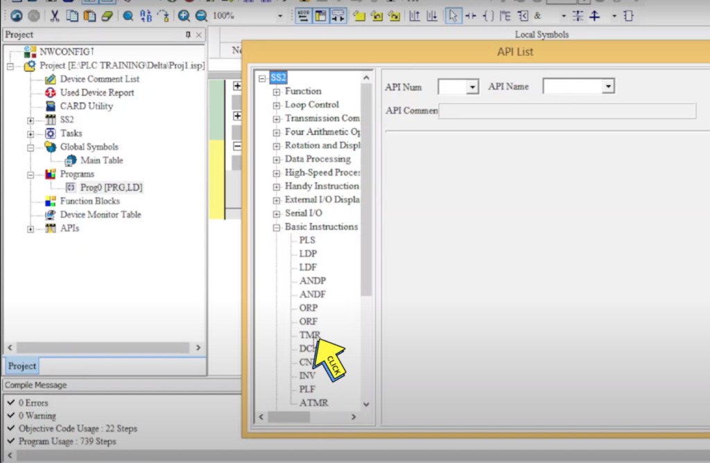
Click on “Basic Instructions.”
Step 4:-
Click on “TMR”
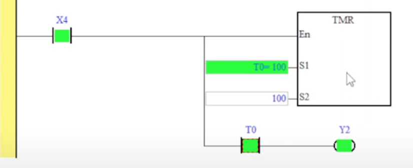
What is the Timer in a ladder logic diagram in Delta PLC ISPSoft Programming Software?.
When TMR instruction is executed, the designated coil of the timer will be On and the timer will start to time. When the set value in the timer is reached (present ≥ set value), the contact will be:
Section - 3 PLC Counter Programming for Beginners.
Step 1 :-
Click on “Rung”
Step 2 :-
Click on “new Tap”
Step 3:-
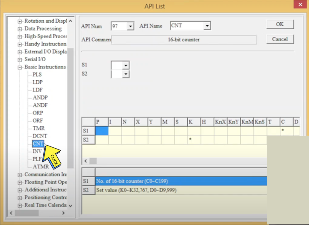
Click on “Basic Instructions.”
Step 4:-
Click on “CNT”
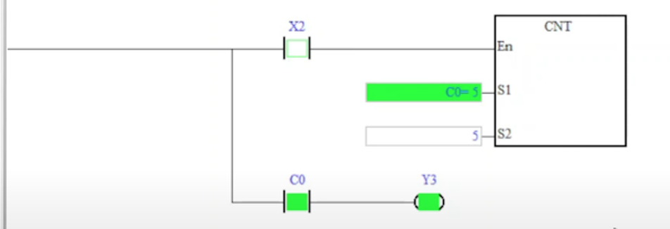
What is Counter in delta PLC Programming?
When the CNT instruction goes from Off to On, the designated counter coil will be driven, and the present value in the counter will plus 1. When the counting reaches the set value (present value = set value), the contact will be
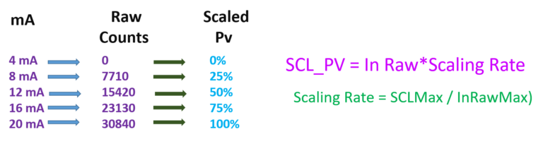
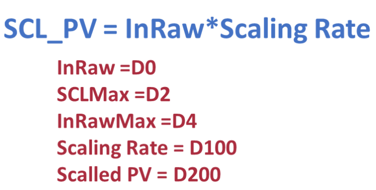
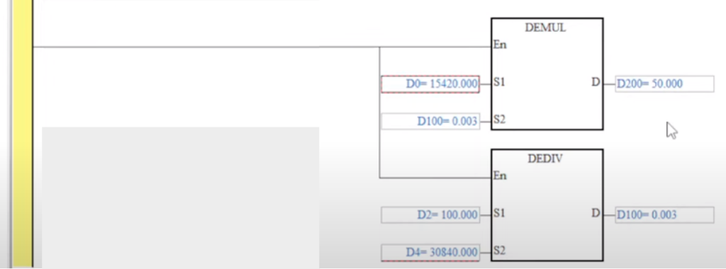
Section - 4 How to scale Analog Input 4-20 mA signal?
What scaling means is that you convert the raw value from the analog input to engineering or Scale value
Section -5 DECIMAL TO FLOATING POINT USING DELTA PLC - Addition, Subtraction, Multiply, Division.
Decimal To Floating
Decimal Floating Point :-
Since the binary floating point are not very user-friendly, we can convert it into a decimal floating point for use. Please be noted that the decimal point operation in DVP-PLC is still in binary floating point.
The decimal floating point is represented by 2 continuous registers. The register of smaller No. is for the constant while the register of bigger No. is for the exponent.
Example:-
: Storing a decimal floating point in registers (D1, D0) Decimal floating point = [constant D0] × 10 [exponent D1 ] Constant D0 = ±1,000 ~ ±9,999 Exponent D1 = -41 ~ +35
The constant 100 does not exist in D0 due to 100 is represented as 1,000 × 10-1. The range of decimal floating point is ±1175 × 10-41 ~ ±3402×10+35.
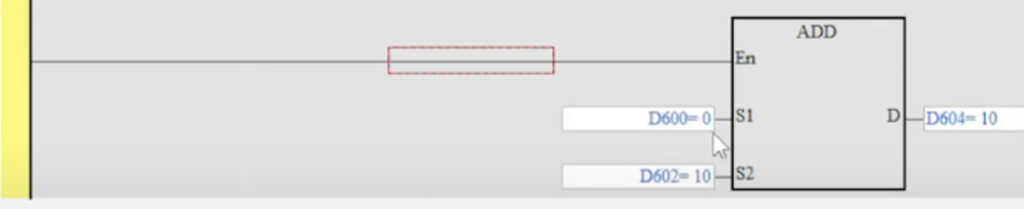
Addition
S1: Summand S2: Addend D: Sum
1.If S1, S2 and D are used in device F, only 16-bit instruction is applicable. 2. See the specifications of each model for their range of use. 3. Flags: M1020 (zero flag); M1021 (borrow flag); M1022 (carry flag) 4. This instruction adds S1 and S2 in BIN format and store the result in D. 5. The highest bit is symbolic bit 0 (+) and 1 (-), which is suitable for algebraic addition, e.g. 3 + (-9) = -6. 6. Flag changes in binary addition.
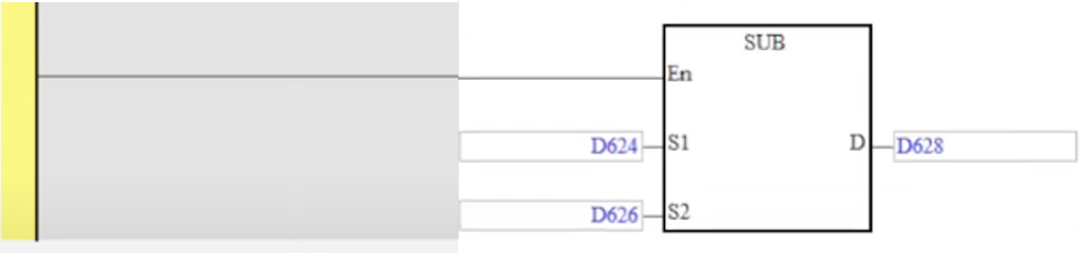
Subtraction
S1: Minuend S2: Subtrahend D: Remainder
1. If S1, S2 and D are used in device F, only 16-bit instruction is applicable. 2. See the specifications of each model for their range of use. 3. Flags: M1020 (zero flag); M1021 (borrow flag); M1022 (carry flag) 4. This instruction subtracts S1 and S2 in BIN format and stores the result in D. 5. The highest bit is symbolic bit 0 (+) and 1 (-), which is suitable for algebraic subtraction. 6. Flag changes in binary subtraction
7. For flag operations of SUB instruction and the positive/negative sign of the value, see the explanations in ADD instruction on the previous page.
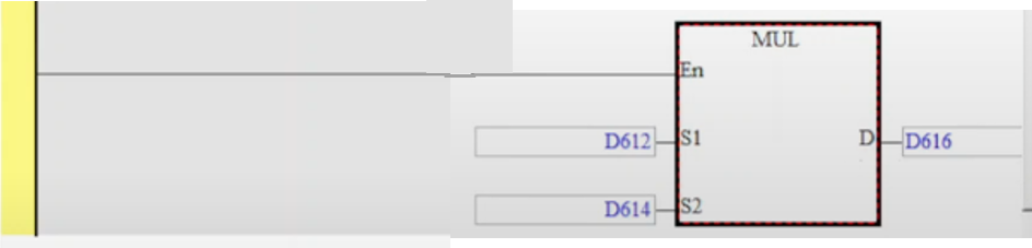
Multiplication
S1: Multiplicand S2: Multiplicator D: Product
1. If S1 and S2 are used in device F, only 16-bit instruction is applicable. 2. If D is used in device E, only 16-bit instruction is applicable. 3. In 16-bit instruction, D occupies 2 consecutive devices. 4. In 32-bit instruction, D occupies 4 consecutive devices. 5. See the specifications of each model for their range of use. 6. This instruction multiplies S1 by S2 in BIN format and stores the result in D. Be careful with the positive/negative signs of S1, S2 and D when doing 16-bit and 32-bit operations.
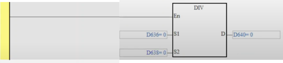
Division
S1: Dividend S2: Divisor D: Quotient and remainder
1. If S1 and S2 are used in device F, only 16-bit instruction is applicable. 2. If D is used in device E, only 16-bit instruction is applicable. 3. In 16-bit instruction, D occupies 2 consecutive devices. 4. In 32-bit instruction, D occupies 4 consecutive devices. 5. See the specifications of each model for their range of use. 6. This instruction divides S1 and S2 in BIN format and stores the result in D. Be careful with the positive/negative signs of S1, S2 and D when doing 16-bit and 32-bit operations. 7. This instruction will not be executed when the divisor is 0. M1067 and M1068 will be On and D1067 records the error code 0E19
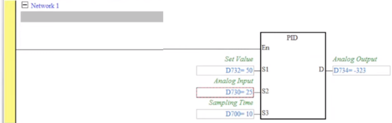
Section -6 Delta PLC PID Control Loop Programming Training What is PID and how does it work?
What is PID and how does it work?
S1: Set value (SV) S2: Present value (PV) S3: Parameter D: Output value (MV)
1. In the 16-bit instruction, S3 will occupy 20 consecutive devices; in the 32-bit instruction, S3 will occupy 21 consecutive devices. 2. See the specifications of each model for their range of use. 3. See the Remarks below for the times of using PID instruction allowed in the program. 4. This instruction is specifically for PID control. PID operation will be executed by the scan only when the sampling time is reached. PID refers to “proportion, integration and differential”. PID control is widely applied to many machines, pneumatic and electronic equipments. 5. For the 16-bit instruction, the parameters are S3 ~ S3+19; for the 32-bit instruction, the parameters are S3 ~ S3+20. After all the parameters are set up, PID instruction will start to be executed and the results will be stored in D. D has to be the data register area without latched function. (If you wish to designate a latched data register area, place the data register in the latched area at the beginning of the program and clear it as 0.)
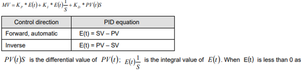
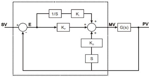
PID Equations:-
The PID operation is conducted according to the speed and the differential PV.
The PID operation has three control directions: automatic, foreward and inverse. Forward or inverse are designated in S3 +4. Other relevant settings of PID operation are set by the registers designated in S3 ~ S3 +5.
Basic PID equation:-
the control direction is selected as forward or inverse, ( )tE will be regarded as “0″. The equation above illustrates that this instruction is different from a general PID instruction by the variable use of the differential value. To avoid the flaw that the transient differential value is too big when a general PID instruction is executed for the first time, our PID instruction monitors the differentiation status of the PV. When the variation of PV is too big, this instruction will reduce the output of MV.
S is differentiation, referring to “PV – previous PV / sampling time”. 1 / S is integration, referring to “(previous integral value + error value) × sampling time”. G(S) refers to the device being controlled.
Section -7 Delta DIAView SCADA Communication with DVP14SS2 PLC
Step 1 :-
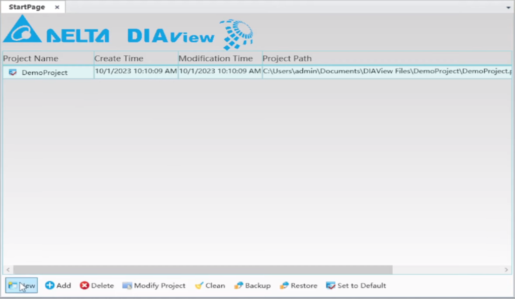
Open “DELTA DIAView “
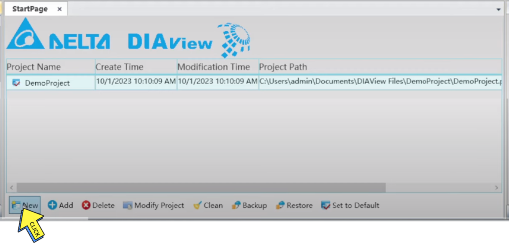
Step 2 :-
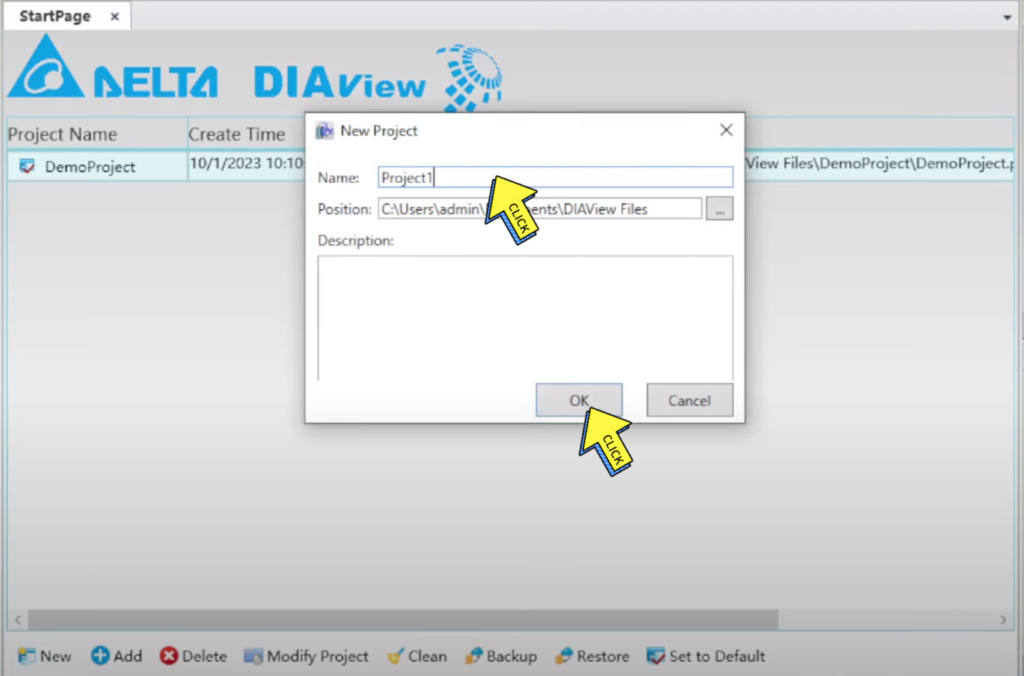
Click on “New “
Step 3 :-
Enter your “project name”
Click on “OK”
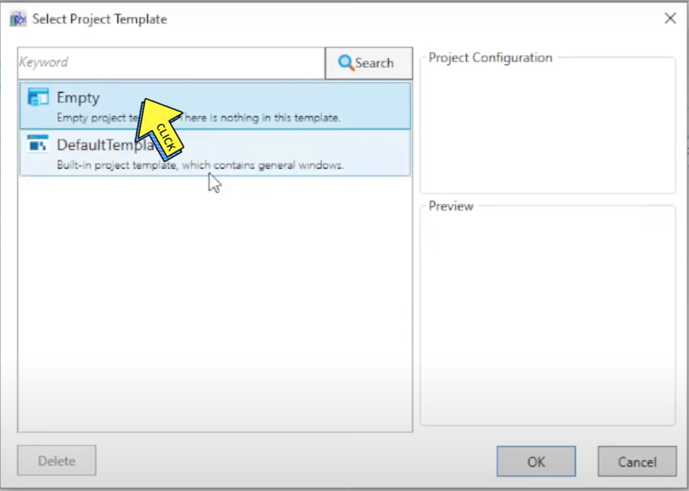
Step 4 :-
Click on “Empty “ and
Click on “Ok button”
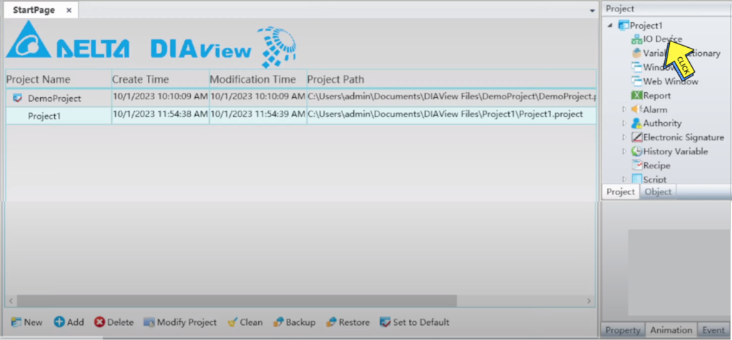
Step 5 :-
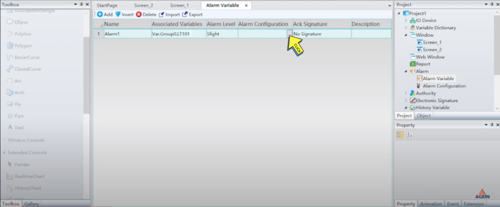
Click On “IO Device”
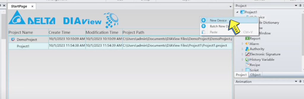
Step 6 :-
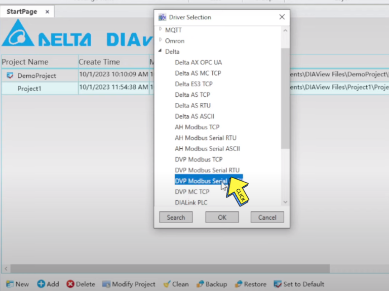
Click On “New Device”
Step 7 :-
Select “DVP Modbus Serial ASCII”
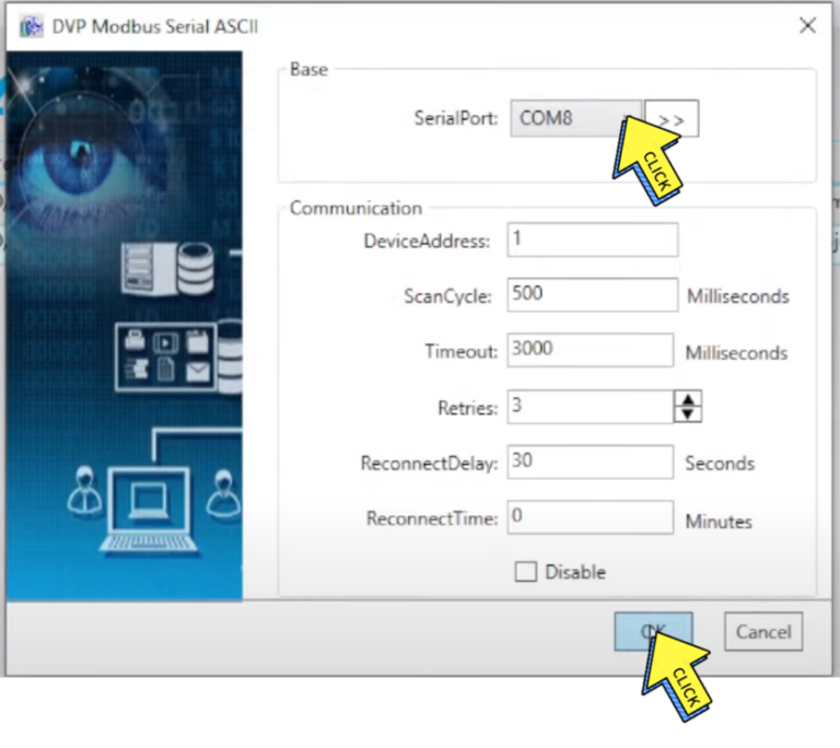
Step 8 :-
Check your “Serial Port”
Click on “ok button”
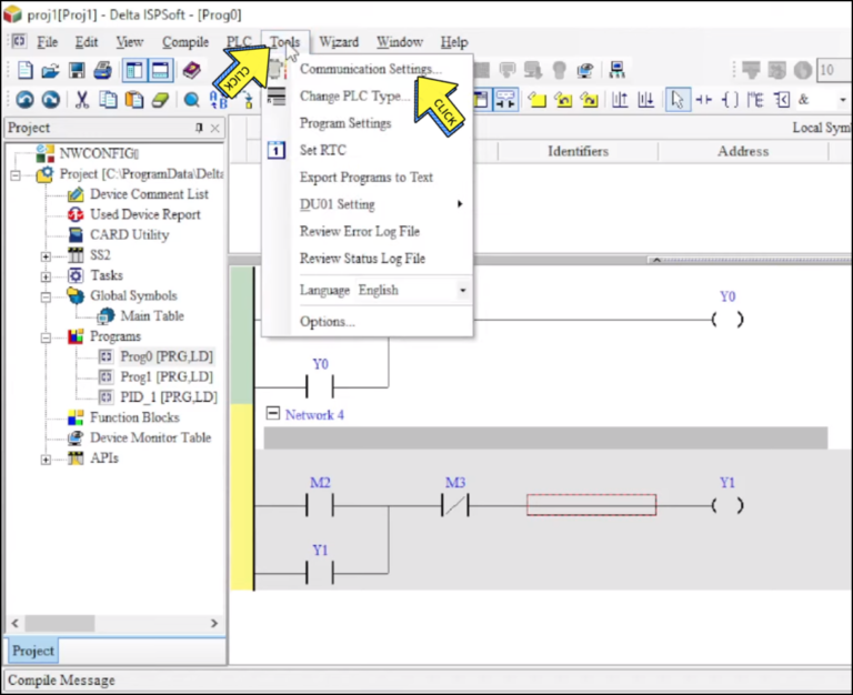
Step 9 :-
Click on “Tool and Communication Settings”
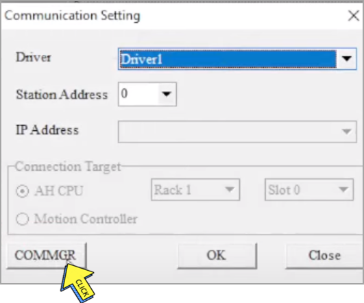
Step 10 :-
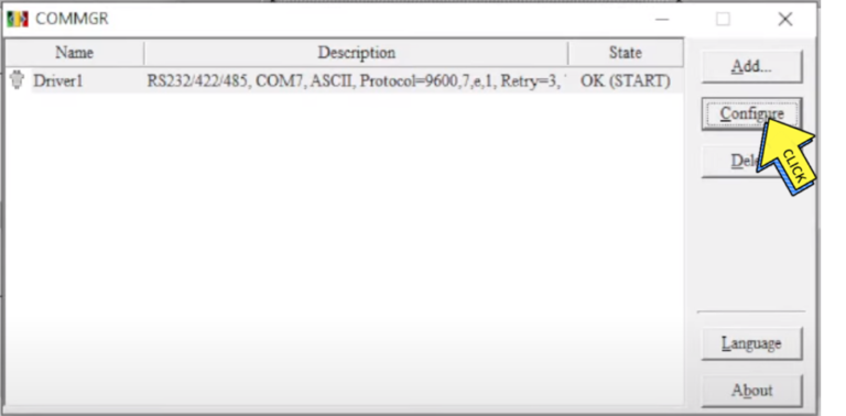
Click on “COMMGR”
Step 11 :-
Click on “Configure”
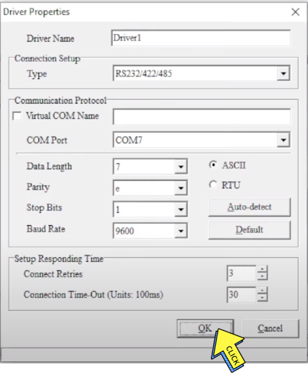
Step 12 :-
Click on “Ok button”
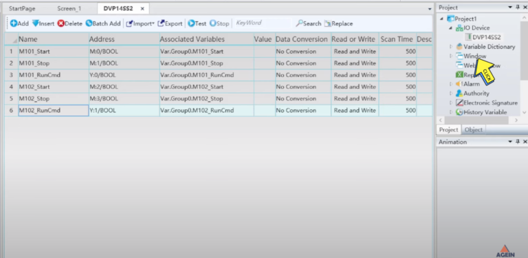
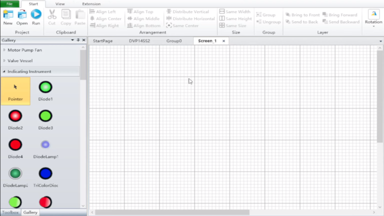
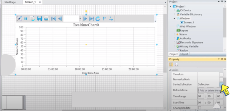
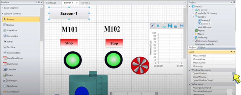
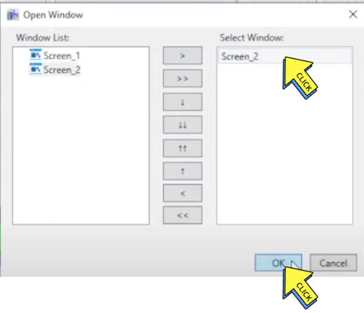
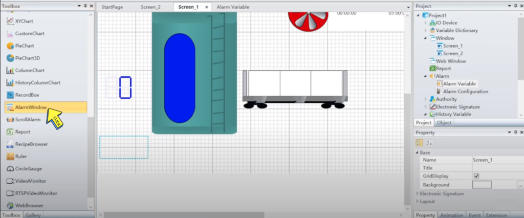
Create SCADA Screen
Step 1 :-
Click on “Window”
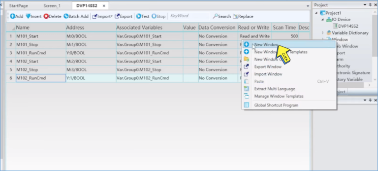
Step 2 :-
Click on ” New Window”
Step 3 :-
SCADA screen created
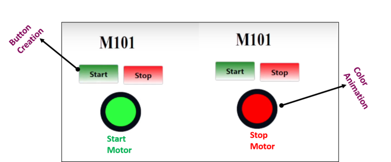
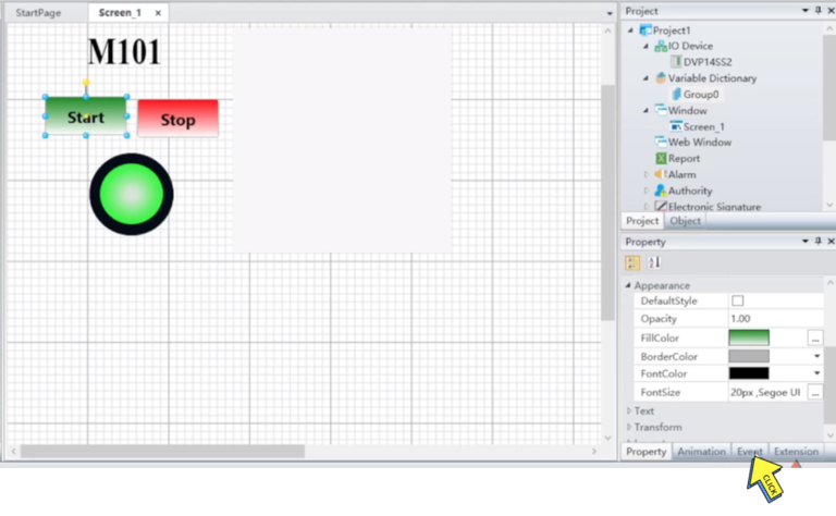
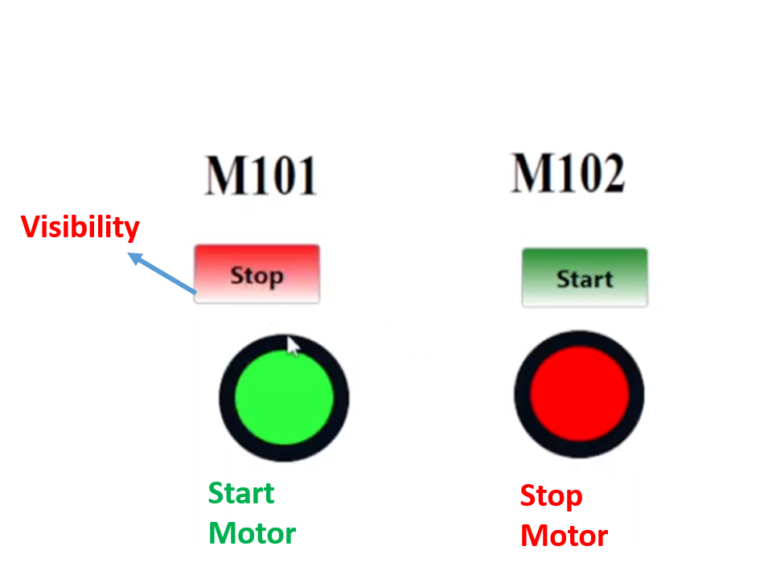
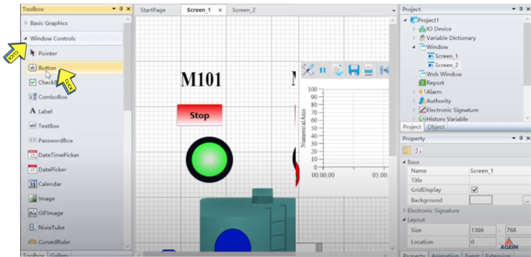
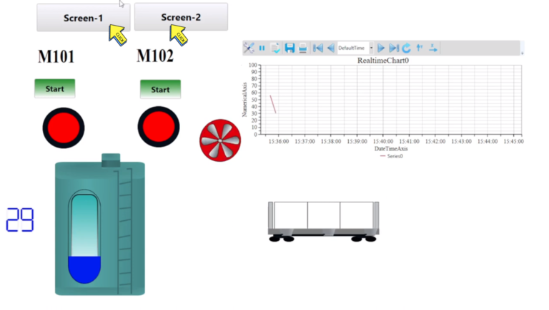
Button Creation & Colour Animation
Section -8 Visibility & Colour Filling Animation.
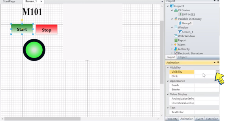
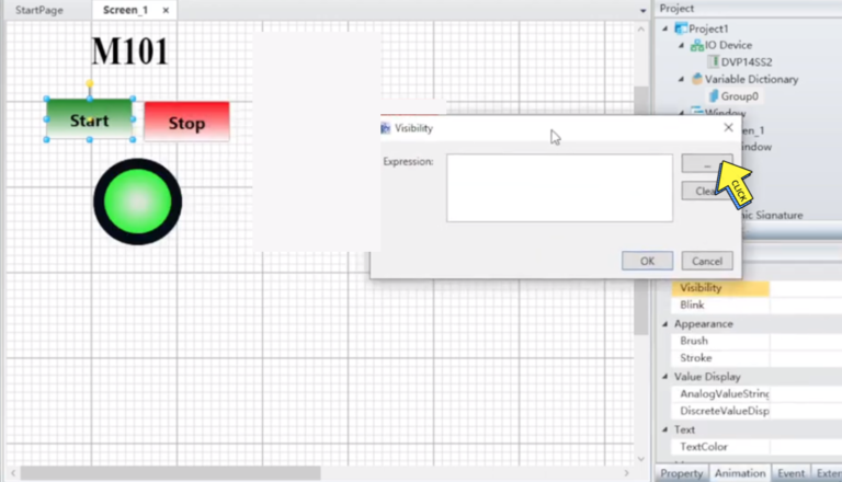
Visibility Animation in SCADA
Step 1 :-
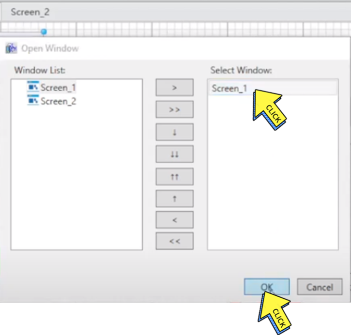
Click on “Event”
Step 2 :-
Click on “Visibility”
Step 3 :-
Click on “Expression”
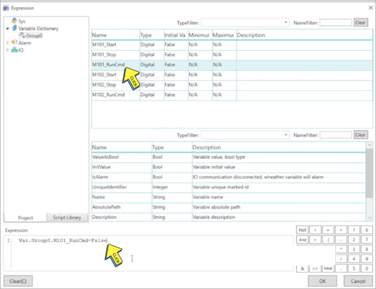
Step 4 :-
Select on “RunCMD” and
Type Expression ” Var. Group0. M101_RunCMD=False”
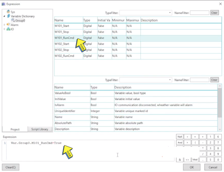
Step 5 :-
Select on “RunCMD” and
Type Expression ” Var. Group0. M101_RunCMD=True”
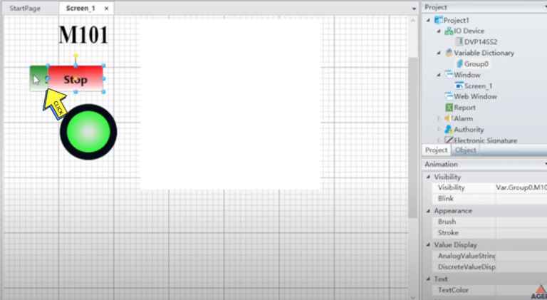
Step 6 :-
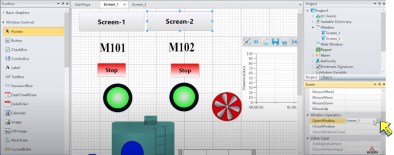
Add the “both buttons”
Step 7 :-
The Button “Visible”
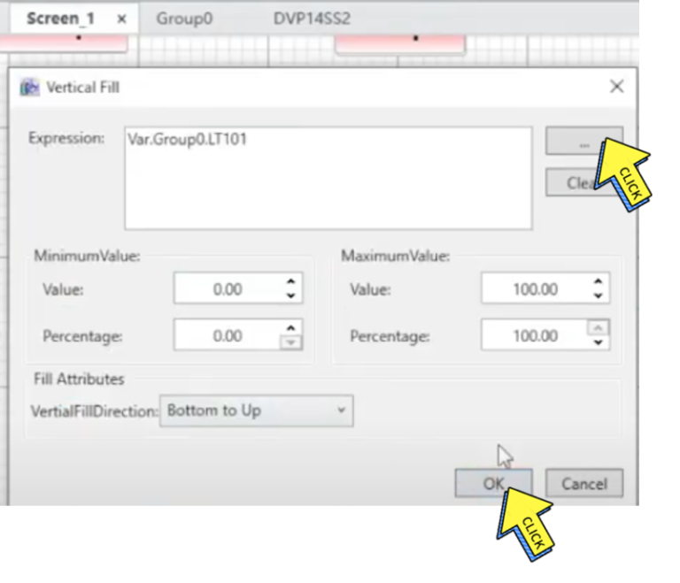
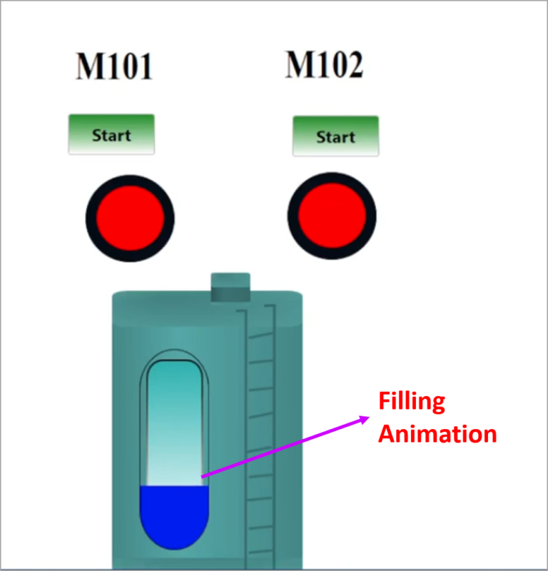
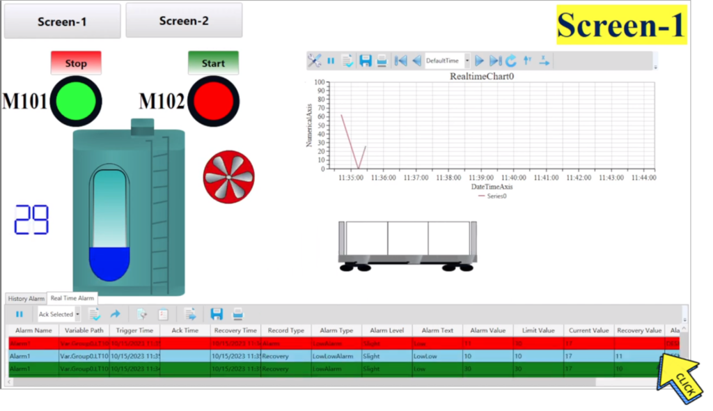
Filling Animation in SCADA
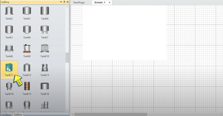
Step 1 :-
Click on “Tank11”
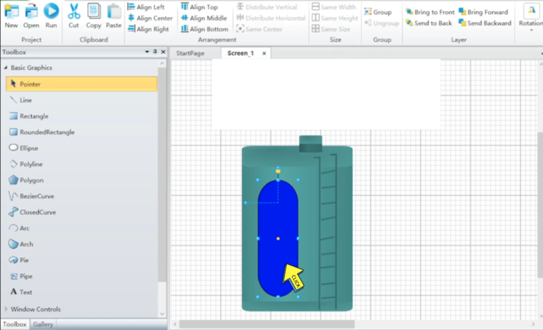
Step 2 :-
Right Click on “Blue”
Step 3 :-
Select your “Tag” and
Click on “Okay button”
Step 3 :-
Filling Animation in SCADA
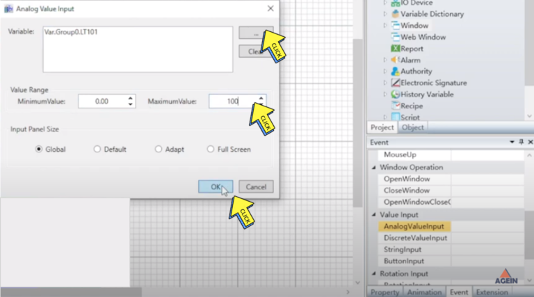
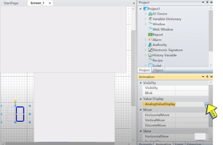
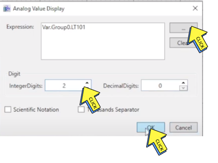
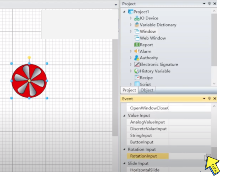
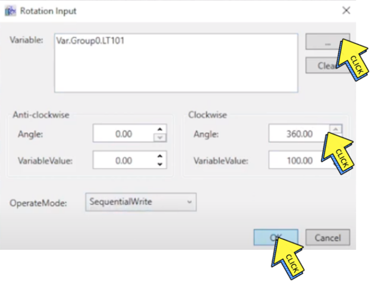
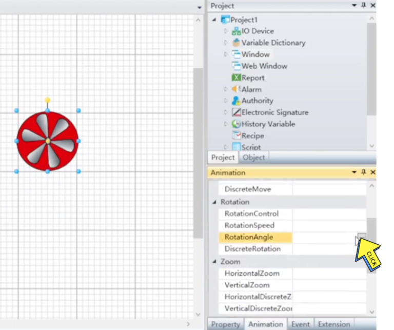
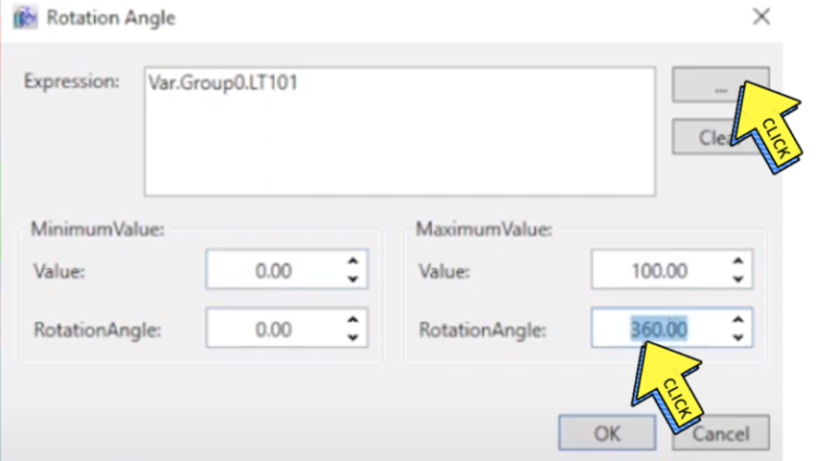
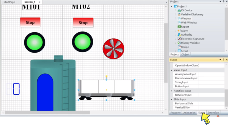
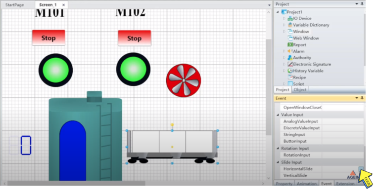
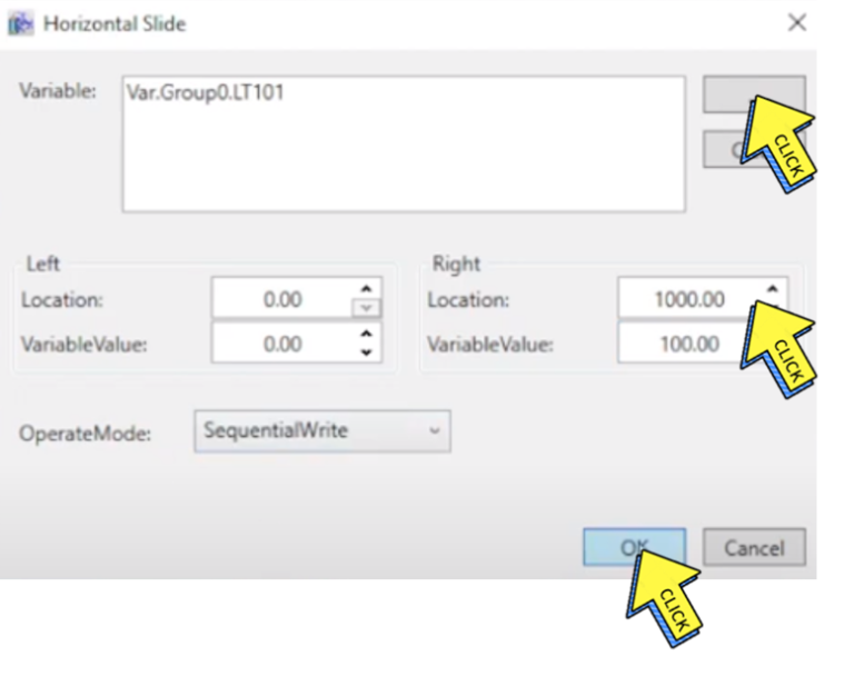
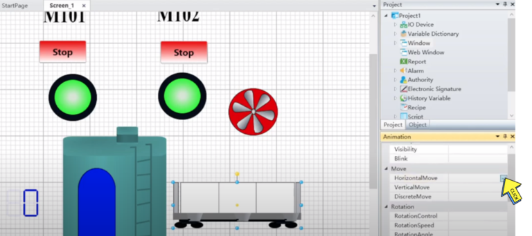
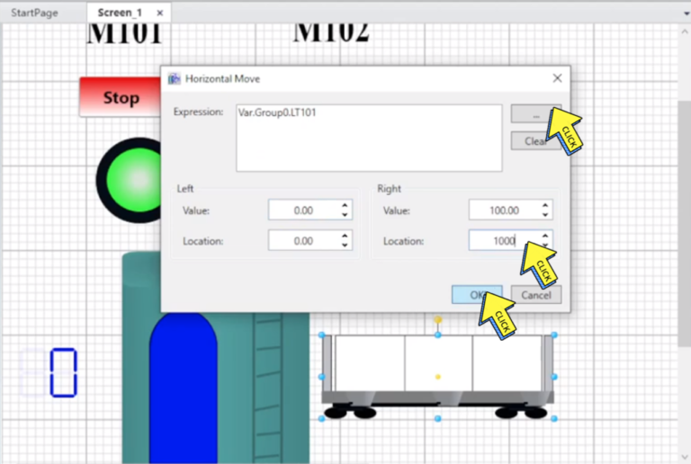
Section - 9 Rotation & Movement Animation Analog Numerical Value Display