Sinking & Sourcing in PLC Input / Output Wiring Type
How to set IP address in Micro820PLC
How to make a simple Animation SCADA Software
Micro820 PLC Communication with FactoryTalk View SE
Alarm Programming-Fault Capturing Example in CCW using Set & Reset Coil
How to Start/Stop & send Reference to VFD via PLC\SCADA VFD parameter setting
How to communicate powerflex4m VFD with Micro850 PLC over Modbus RS485 start\stop via Modbus RS485
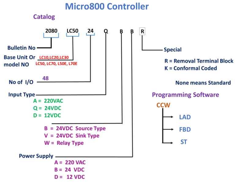
Section-1: Micro800 programming Step-by-step PLC
Introduction PLC
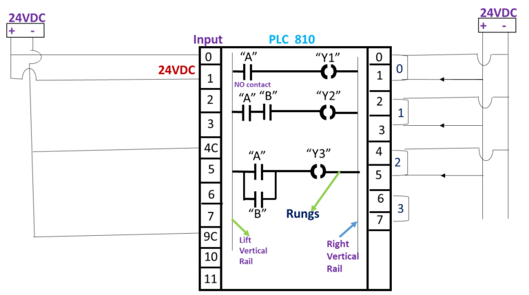
Vertical rails, Rung Ladder, Ladder diagrams are specialized schematics commonly used to document industrial control logic systems. They are called “ladder” diagrams because they resemble a ladder , with two vertical rails (supply power) and as many “rungs” (horizontal lines) as there are control circuits to represent.
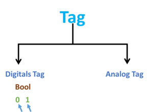
what is tag in PLC ?
Digital Tags:
Tag is a name you assign to an address of device/PLC. It is also called “variable” or “symbol” depending on the manufacture of the device/PLC
Data Types of Tag:
Bool : 0 or 1 true or false
What is Normally Open (NO) Contact?
Normally open contact (NO) is true when the input status bit controlling the contact is 1.
What is Normally Open (NO) Contact?
What is Direct coil?
PLC programming explained.
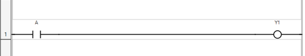
If “A” is true then “Y1” true
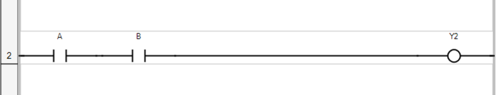
If “A” is true AND “B” is true then “Y1” true
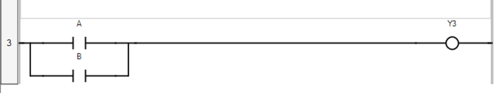
If “A” is true OR “B” is true then “Y3” true
Section-2: PLC Basics Ladder Logic
If “A” true then “Y1” true.
If “A” true AND “B” then “Y2” true.
If “A” true OR “B” then “Y3” true.
SET / RESET or LATCH/UNLATCH Coils.
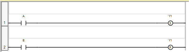
If “A” push button is pressed then “Y1” true & True until “B” Push button is pressed.
Set Coil :- Coils are graphic components of Ladder Diagram (LD) program that represent the assignment of an output or of an internal variable. In LD programs, a coil represents an action. Set coils support a Boolean output of a connection line Boolean state.
The associated variable is set to TRUE when the Boolean state of the left connection becomes TRUE. The output variable keeps this value until an inverse order is made by a Reset coil.
Reset Coil :- Coils are graphic components of Ladder Diagram (LD) programs that represent the assignment of an output or of an internal variable. Reset coils support a Boolean output of a connection line Boolean state.
The associated variable is reset to FALSE when the Boolean state of the left connection becomes TRUE. The output variable keeps this value until an inverse order is made by a Set coil.
Section-3: What are Analog Tags in PLC?
Digital Signals
Digital Input signals are used to represent items that only have two (2) state, such as… ON (binary 1) or OFF (binary 0) states. Similarly, Digital output signals are used to control items that again only have two states, such as… START or STOP a device.
So, a digital signal is something like telling if a door is open or not.
Analog signals
Analog signals are variable, they have multiple states. Analog input signals can represent such items as temperature or level or rate of flow.
Analog output signals are also variable and can be used for such things as opening a valve to a desired position. Then, an analog signal is something like telling how much the door is open (or closed). In our day to day life, we mainly do analog measurements and all analog signals includes the digital ones like a door is 0%=closed or 100%=open.
Analog Tag :-
Sint =short integer = 8 bits (-128 to + 127)
Int = integer = 32 bits (-32,768 to +32,767)
Dint =Double integer = 32 bits (-2147,483648 to +2147,483647)
Real= (+/-3.402823E38 to +/-1.1754944E-38)
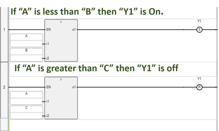
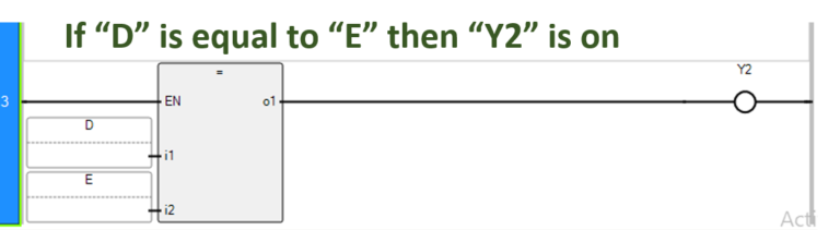
Expression:-
Section-4: What are Arithmetic Operations in PLC Programming?
An arithmetic operator is a mathematical function that takes two operands and performs a calculation on them. They are used in common arithmetic and most computer languages contain a set of such operators that can be used within equations to perform a number of types of sequential calculation.
These operators are + (addition),-(subtraction), * (multiplication),/ (division),and % (modulo)
Addition
Addition- The capability to add one piece of data to another.
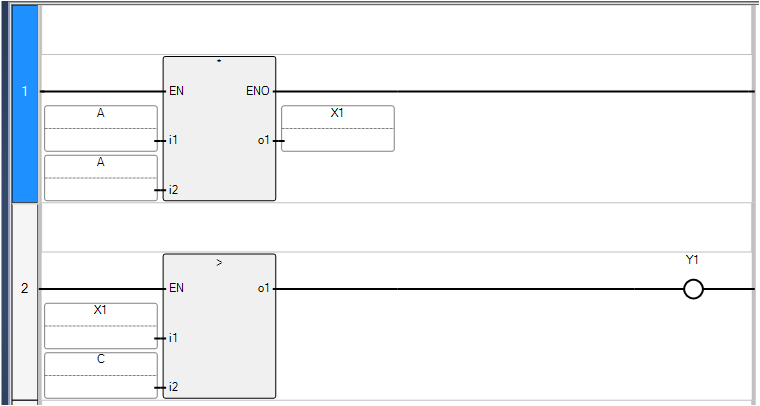
If (“A”+”B”) is greater than “C” then “Y1” on
Subtraction
Subtraction – The capability to subtract one piece of data from another.
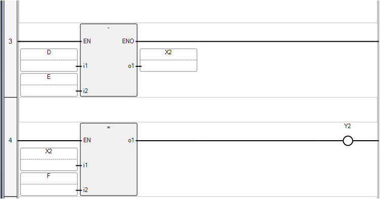
If (“D”-“E”)=”F” then “Y2″on
Multiplication
Multiplication – The capability to multiply one piece of data by another.
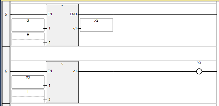
If (“G”*”H”) is less than “I” then “Y3” on
Division
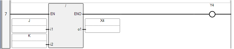
Division –
The capability to divide one piece of data by another.
Section- 5 Timers Instructions
Types of Timers
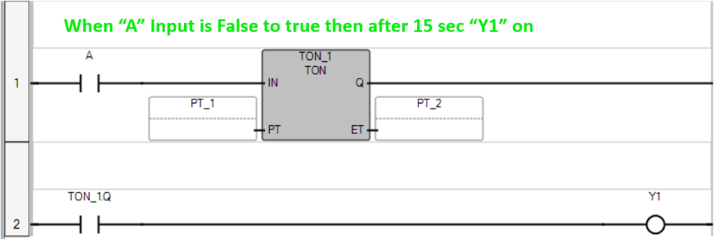
Ton – ON Delay Timer
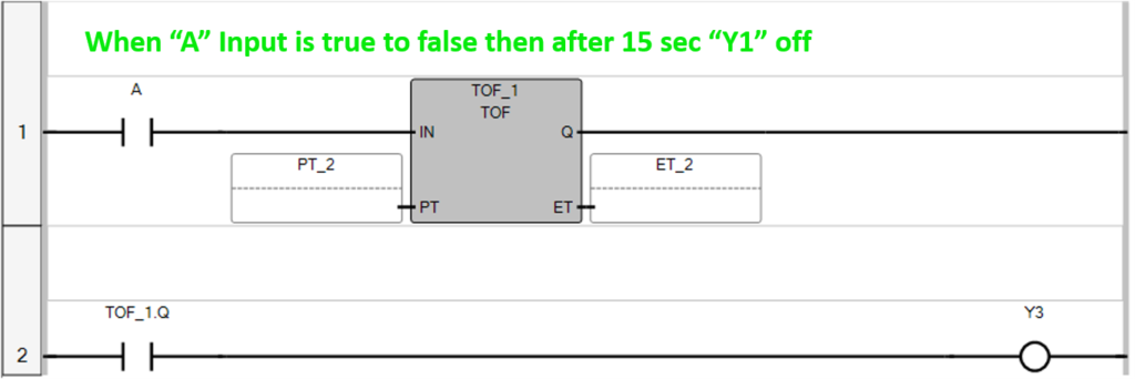
Toff – OFF Delay Timer
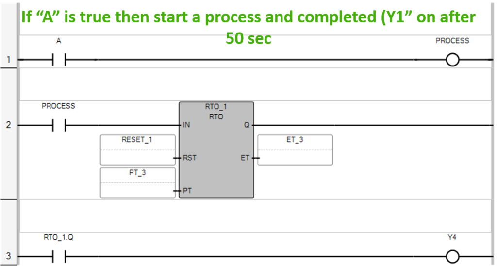
RTO – Retentive Timer
TON Timer
ON delay Timer –
Timer ON Delay, Timer starts when the timer trigger bit is true, and the timer output bit turns ON when the setup time has passed.
Tof Timer
OFF delay Timer –
OFF Delay Timer, the timer output bit turns OFF when the setup time has passed after the timer input bit had turned OFF.
RTO Timer
Retentive Timer (RTO) –
The main function of the RTO is used to hold or store the set (accumulated) time. RTO is used in the case when there is a change in the rung state, power loss, or any interruption in the system.
Section- 6 Counter Instructions
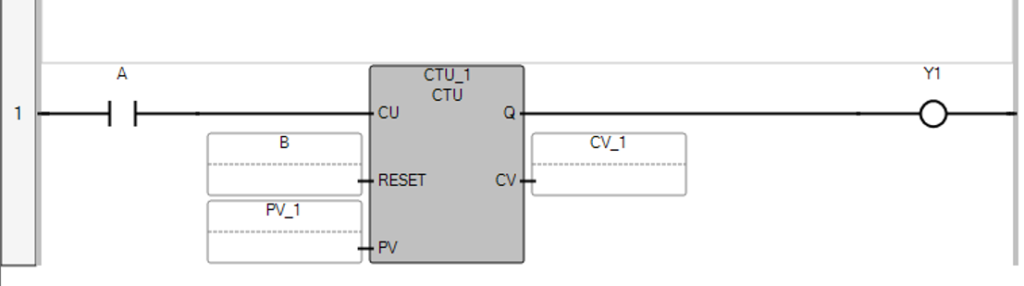
Count Up (CTU) Counter
CTU (count up) Counter :
Counts integers from 0 up to a give value, 1 by 1.
Counts upward. When the CU input bit is TRUE then count upward in increments of one. when the CU input bit is FALSE then hold the counter value at the same value.
If we press “A” Push button 10 times then after 10 count “Y1” lamp is switch on. & when we Press “B” Push button then counter reset Counter and “Y1” Lamp switch off.
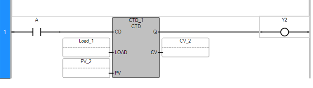
Count Down (CTD) Counter
Counts down :
when the CU input bit is TRUE then count down in decrements of one. when the CU input bit is TRUE then hold the counter value at the same value. Counts integers from a given value down to 0, 1 by 1
When we press “B” push button then counter load Counter Value=10.
And when we press “A” push button 10 times one-by-one CV count down to zero.
When CV is Zero then “Y1” lamp is on.
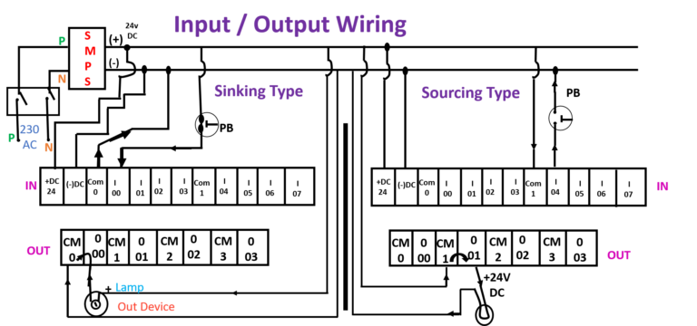
Section- 7 Sinking & Sourcing in PLC Input /Output Wiring type
Concept of Sinking and Sourcing
Sinking Input and Output “Sinking means common connected with the (-ve terminal)”
A sinking input card requires power to be sourced to the input to turn it “ON” The same way a sinking output card requires power to be sourced to the load to turn it “ON”.
Sourcing Input and Output “Sourcing means common connected with the (+ve terminal)”
A sourcing input card required a ground connection to the input to turn it “ON”, same way a sourcing output card requires a ground connection to the load to turn it “ON”.
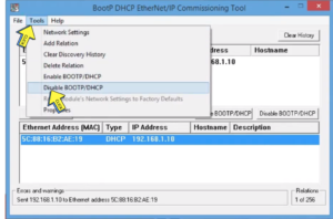
Section- 8 How to Set IP address in Micro820 PLC
BOOTP/DHCP CONFIGURATION
How to find ethernet device on ethernet network through BOOTP / DHCP TOOL.
What is BOOTP/DHCP: BOOTP is bootstrap protocol & DHCP is dynamic host configuration protocol.
What should do for not forgot their IP address after power reset of plc.
How to search device on RSLINC classic software for PLC communication.
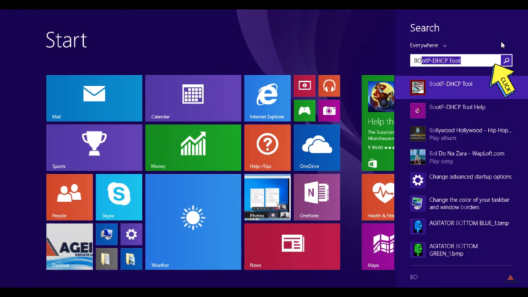
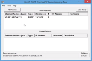
Step 1 –
Search On “BOOTP/DHCP TOOL”
Step 2 –
Select a “network interface”.
Step 3 –
Search On your PLC “MAC ID”
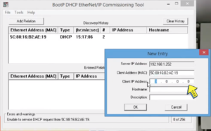
Step 4 –
Set on ” Client IP Address”
Step 5 –
Temporary “IP” Set in DHCP
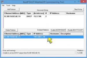
Step 6 –
Set on “IP address”
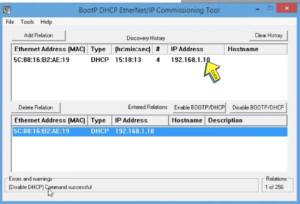
Step 7 –
Click on “Tools button” and
Select “Disable BOOTP/DHCP”
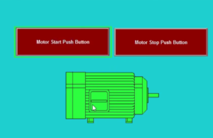
Section- 9 How to make a Simple Animation SCADA Software?
Create button in SCADA
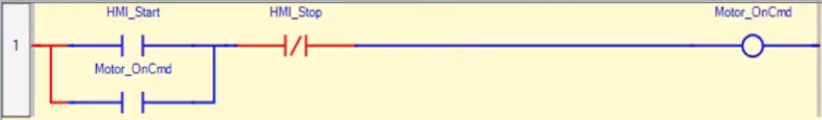
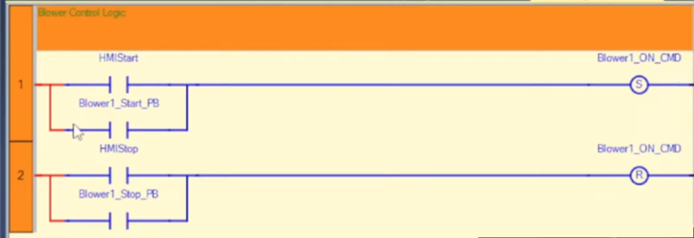
HMI Start/Stop Logic Program
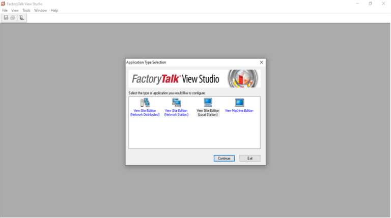
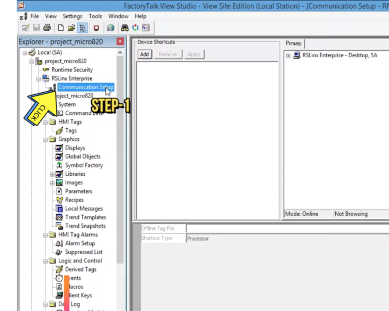
Section-10 Micro820 PLC Communication with FACTORYTALK VIEW SE
Step 1 –
Open “Factory Talk View Studio
Step 2 –
Click on “Communication Setup”
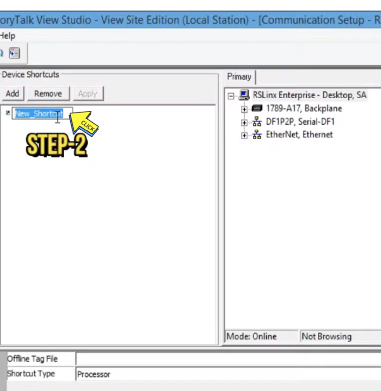
Step 3 –
Click on “Add button” and
Type on “Project Name”.
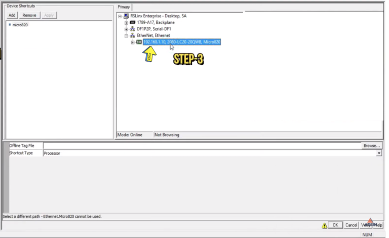
Step 4 –
Search on “PLC IP address”
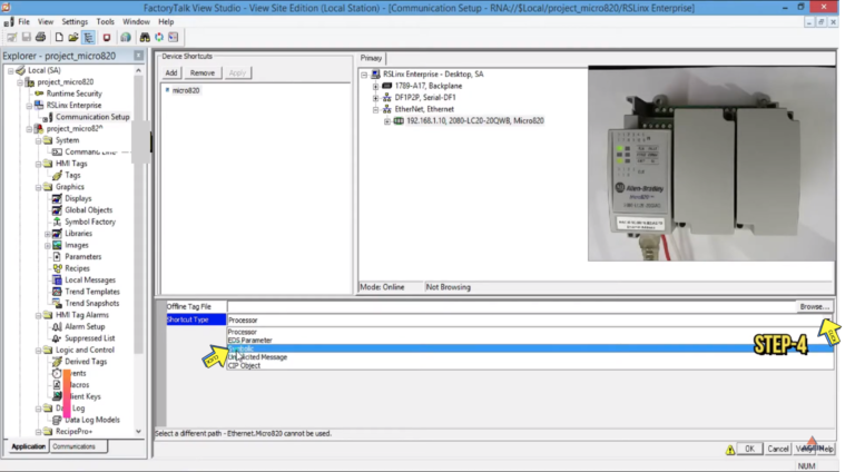
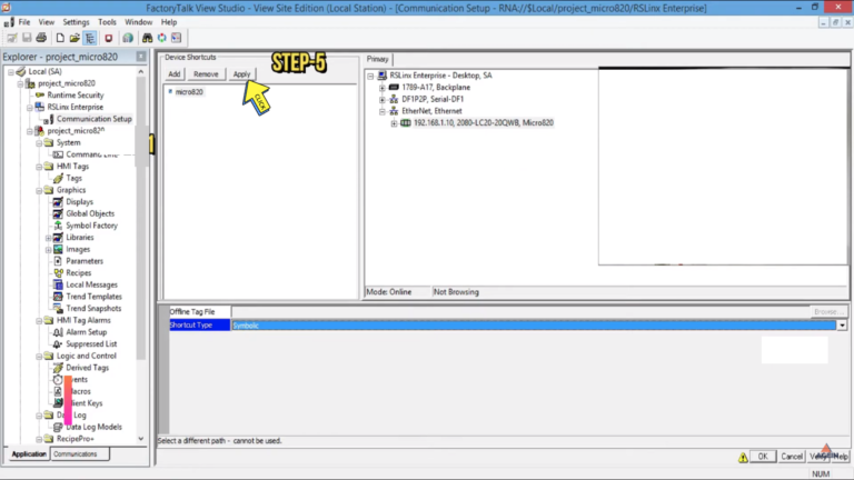
Step 5 –
Click on “Shortcut type” and
Select “Symbolic”
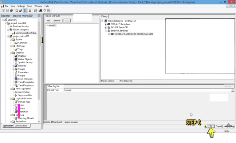
Step 6-
Click on “Apply button ”
Step 7 –
Click on “Okay button ”
How to launch a Client in FTV SE SCADA.
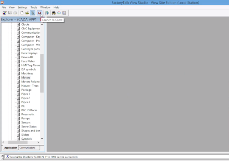
Step 1 –
Click on “Launch SE Client ”
Step 2 –
Open “Factory Talk View Site Edition”
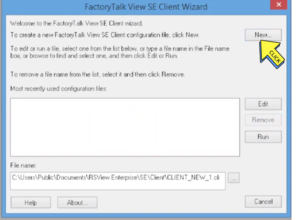
Step 3 –
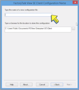
To Create a new FactoryTalk View SE Client configuration. Click New
Step 4 –
Type the name of a new configuration file. Next>>
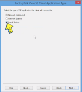
Step 5 –
Select the type of SE application the client will connect To.
Select On ” Local Station” Next>>
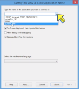
Step 6 –
Select Your “Project “ Next>>
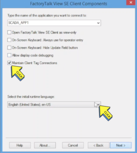
Step 7 –
Click on “Maintain Client Tag Connections”
Select the initial runtime language Next >>
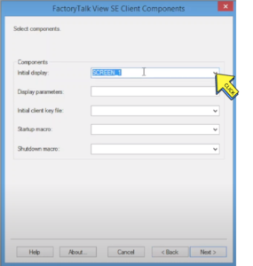
Step 8 –
Components Initial display Next>>
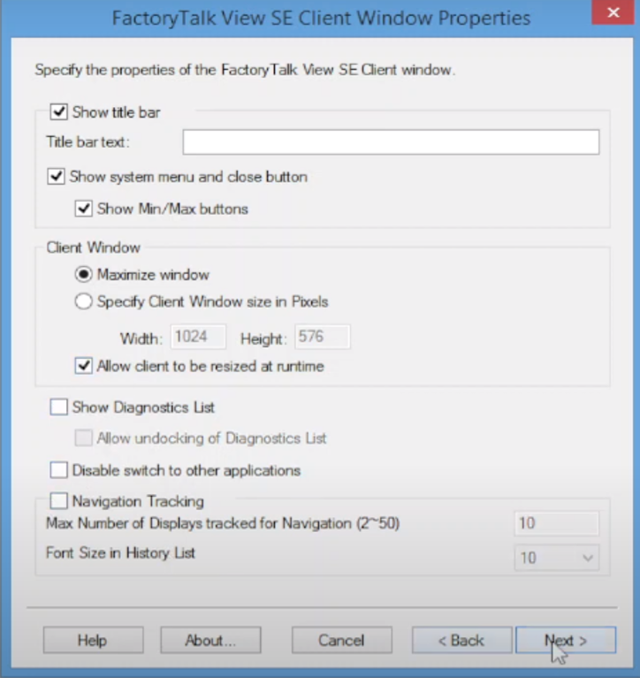
Step 9 –
Specify the properties of the Factory Talk View SE Client window.
Select on “Tick”
Next>>
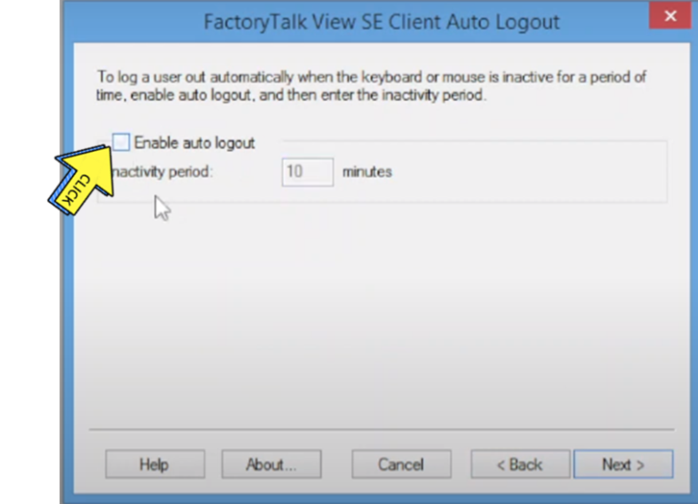
Step 10 –
Untick on “Enable auto logout”
Next>>
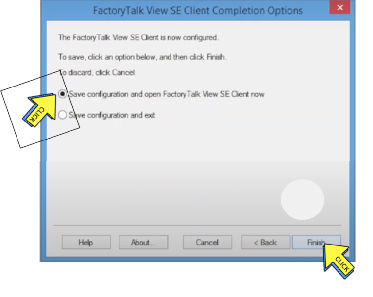
Step 11 –
Tick on “Save configuration and open FactoryTalk View SE Client now.
Click on “Finish button“
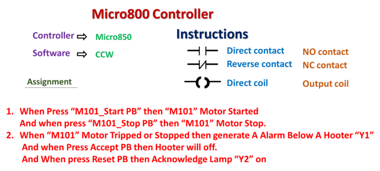
Section- 11 : Alarm Programming- Fault Capturing Example in CCW using Set & Reset Coil
Set Reset Programming
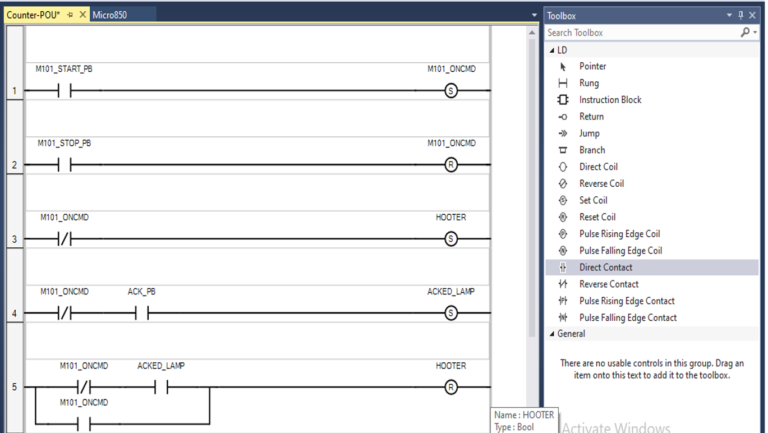
When press“M101_StartPB” then “M101” Motor started AND when press “M101_stop PB” then “M101” Motor Stop.
When “M101” Motor Tripped or Stopped then generate A Alarm Below Hooter “Y1” And when press Accept PB then Hooter will Off. A Acknowledged Lamp “Y2” On. And when press Reset PB then if Motor “M101” is off then Again Alarm will generate.
Set Coil:-
Set coils support a Boolean output of a connection line Boolean state.
The associated variable is set to TRUE when the Boolean state of the left connection becomes TRUE. The output variable keeps this value until an inverse order is made by a Reset coil.
Reset Coil :-
Reset coils support a Boolean output of a connection line Boolean state.
The associated variable is reset to FALSE when the Boolean state of the left connection becomes TRUE. The output variable keeps this value until an inverse order is made by a Set coil.
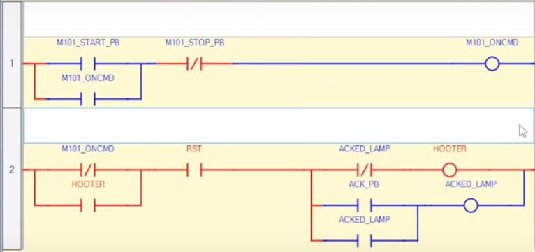
Micro800 PLC Alarm Logic Programming in CCW using basic Instructions, NO & NC Contact & Coil
NC means normally-closed contact.
NO means normally-open contact.
When the relay coil is de-energized, NC contact becomes open, and NO contact closes.
A NC contact or normally closed contact is the exact opposite of NO contact by function. It remains closed until a certain condition is satisfied.
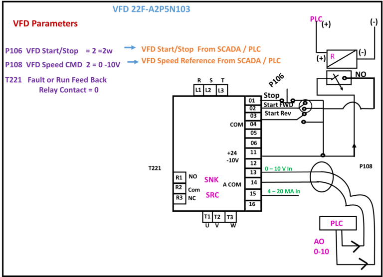
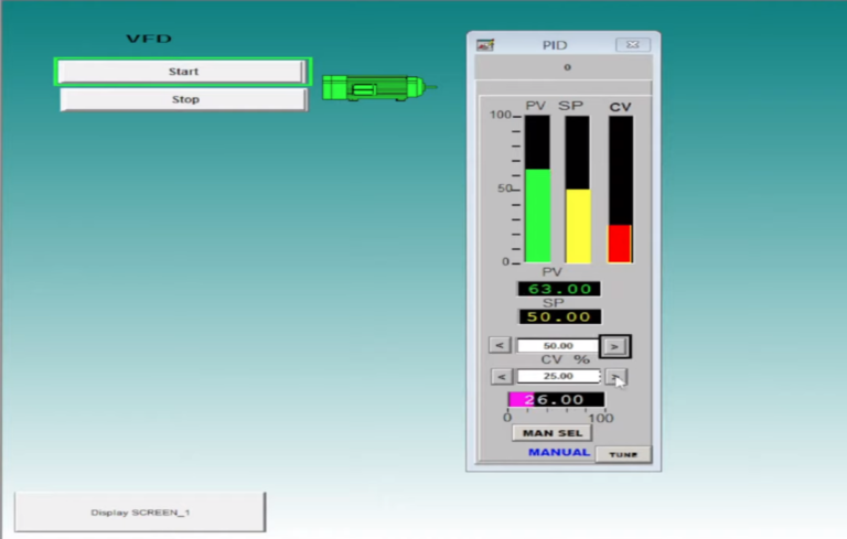
Section-12 : How to start/stop & send Speed Reference to VFD via PLC/SCADA? VFD parameter setting?
VFD Parameters
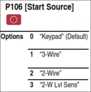
P106 VFD Start/Stop
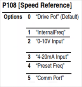
P108 VFD Speed CMD
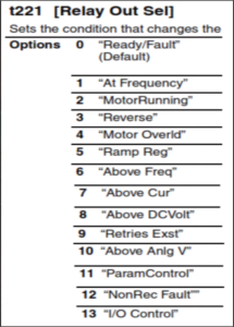
T221 Fault or Run Feed Back
Relay Contact = 0
Ladder Diagram Logic
PID Popup in SCADA
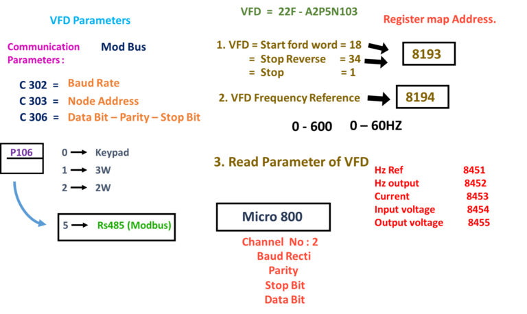
Section-13 : How to communicate powerflex4m VFD with Micro 850 PLC over Modbus RS485? start/stop via Modbus RS485
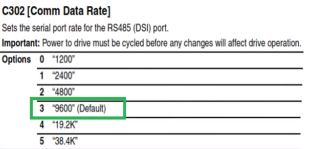
C 302 = Baud Rate :-
Sets the serial port rate for the RS485(DSI) port.
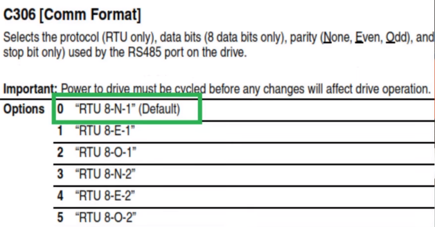
C 306=Data Bit-Parity-Stop Bit :-
Sets the serial port rate for the RS485(DSI) port.
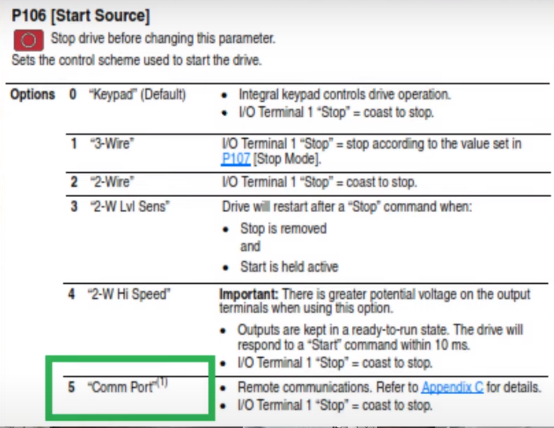
P106 (Strat Source)
Stop drive before changing this parameter.
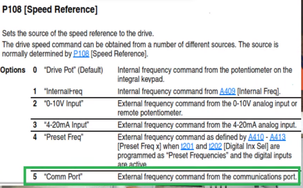
P108 [Speed Reference] :-
Sets the source of the speed reference to the drive.