Chapter:02 PLC Programming Fundamentals of PLC or DCS Control System.
Use relay-type (bit) instructions to monitor and/or control bits in a data file or function file, such as input bits or timer control-word bits. The following instructions are described in this chapter:
Section-A: Bit -Type Ladder Instructions: Basics of Ladder Logic Programming
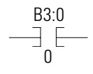
XIC – Examine if Closed also called as “NO Contact”.
If the “Variable Value” of “NO Contact” is true (ie B3:0/0 =1) then the path is connected and current can flow. If the variable of NO Contact is False (ie B3:0/0 =0) then the path is Disconnected and the current can not flow.
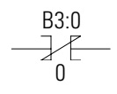
XIO – Examine if Open also known as “NC Contact”.
If the “Variable Value” of “NC Contact” is true (ie B3:0/0 =1) then the path is broken and current cannot flow. If the variable of NC Contact is true (ie B3:0/0 =0) then the path is connected and the current can flow.
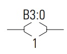
OTE – Output Energize
If all input conditions are connected then output coil will turn on. If any input condition is disconnected then output coil will turn off immediately.
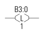
OTL – Output Latch
All input conditions are connected then output coil will turn on and hold. The OTL instructions are retentive output instructions.
OTU – Output Unlatch
All input conditions are connected then output coil will turn off and hold. The OTU instructions are retentive output instructions.
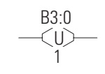
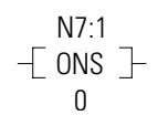
ONS – One Shot
The ONS Storage Bit is the bit address that remembers the rung state from the previous scan. This bit is used to remember the false-to-true rung transition.
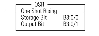
OSR – One Shot Rising
Use the OSR instruction when an event must start based on the false-to-true (rising edge) change of state of the rung.
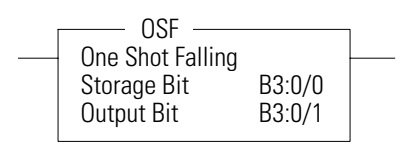
OSF – One Shot Falling
Use the OSF instruction when an event must start based on the true-to-false (falling edge) change of state of the rung.
Section-B : Timer and Counter Instructions
Instruction
TON – Timer, On-Delay
TOF – Timer, Off-Delay
RTO – Retentive Timer On
CTU – Count Up
CTD – Count Down
RES – Reset
Used To:
Delay turning on an output on a true rung
Delay turning off an output on a false rung
Used To: Delay turning on an output on a true rung Delay turning off an output on a false rung Delay turning on an output from a true rung.The accumulator is retentive.
Count up
Count Down
Reset the RTO and counter’s ACC and status bits (not used with TOF timers)
Timer Instructions
Timers in a controller reside in a timer file. A timer file can be assigned as any unused data file. When a data file is used as a timer file, each timer element within the file has three sub-elements. These sub-elements are:
Timer Control and Status
Preset – This is the value that the timer must reach before the timer times out. When the accumulator reaches this value, the DN (Done) status bit is set (TON and RTO only). The preset data range is from 0 TO 32767. The minimum required update interval is 2.55 seconds regardless of the time base.
Accumulator – The accumulator counts the time base intervals. It represents elapsed time. The accumulator data range is from 0 TO 32767.
Timer Value:
EN = Timer Enable Bit
TT = Timer Timing Bit
DN = Timer Done Bit
Preset = Timer Preset Value
Accum = Timer Accumulated Value
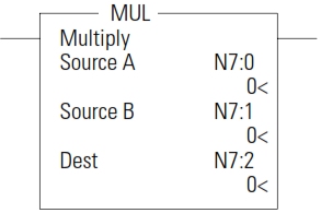
Use the MUL instruction to multiply one value by another value (Source A x Source B) and place the result in the Destination.
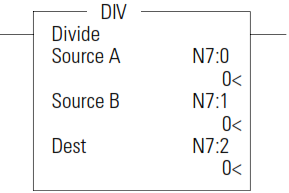
DIV - Divide
Use the DIV instruction to divide one value by another value (Source A/ Source B) and place the result in the Destination. If the Sources are single words and the Destination is directly addressed to S:13 (math register), then the quotient is stored in S:14 and the remainder is stored in S:13. If long words are used, then the results are rounded.
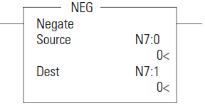
NEG - Negate
Use the NEG instruction to change the sign of the Source and place the result in the Destination.
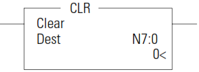
CLR - Clear
Use the CLR instruction to set the Destination to a value of zero.
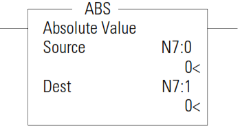
ABS - Absolute Value
The ABS instruction takes the absolute value of the Source and places it in the Destination. The data range for this instruction is -2,147,483,648…2,147,483,647 or IEEE-754 floating point value.
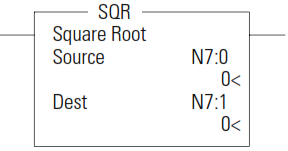
SQR - Square Root
The SQR instruction calculates the square root of the absolute value of the source and places the rounded result in the destination.
The data ranges for the source is -32768…32767 (word) and -2,147,483,648…2,147,483,647 (long word). The Carry Math Status Bit is set if the source is negative. See Updates to Math Status Bits on page 200 for more information.
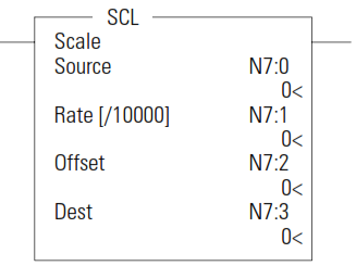
SCL - Scale
The SCL instruction causes the value at the Source address to be multiplied by the Rate (slope) value. The resulting value is added to the Offset and the rounded result is placed in the Destination.
The following equations express the linear relationship between the input value and the resulting scaled value:
scaled value = [(rate x source)/10000] + offset, where
• rate = (scaled max. – scaled min.)/(input max. – input min.) • offset = scaled min. – (input min. x rate) Rate and Offset can both be immediate values. The data range for rate and offset is -32768…32767.
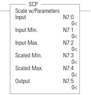
SCP - Scale with
Parameters
The SCP instruction produces a scaled output value that has a linear relationship between the input and scaled values. This instruction solves the following equation listed below to determine scaled output:
y = [(y 1 – y 0 )/(x 1 – x 0 )](x – x 0 ) + y 0
Addressing Modes and File Types can be used as shown in the following table:
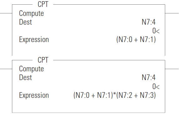
CPT - Compute
The CPT instruction performs copy, arithmetic, logical, and conversion operations. You define the operation in the Expression and the result is written in the Destination. The CPT uses functions to operate on one or more values in the Expression to perform operations such as:
• converting from one number format to another. • manipulating numbers. • performing trigonometric functions.
Instruction
AND – Bit-Wise AND
OR – Logical OR
XOR – Exclusive OR
NOT – Logical NOT
Used To:
Perform an AND operation
Perform an inclusive OR operation
Perform an Exclusive Or operation
Perform a NOT operation
Logical Instructions
The logical instructions perform bit-wise logical operations on individual words.
Using Logical Instructions
When using logical instructions, observe the following:
Source and Destination must be of the same data size (i.e. all words or all long words).
Source A and Source B can be a constant or an address, but both cannot be constants.
Valid constants are -32768…32767 (word) and-2,147,483,648…2,147,483,647 (long word).
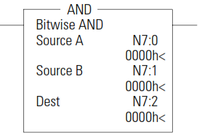
AND - Bit-Wise AND
The AND instruction performs a bit-wise logical AND of two sources andplaces the result in the destination.
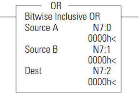
OR - Logical OR
The OR instruction performs a logical OR of two sources and places the result in the destination.
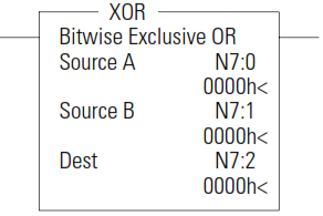
XOR - Exclusive OR
The XOR instruction performs a logical exclusive OR of two sources and places the result in the destination.
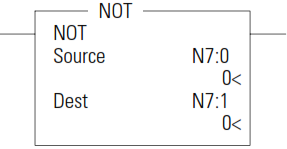
NOT - Logical NOT
The NOT instruction is used to invert the source bit-by-bit (one’s complement) and then place the result in the destination.
Section-F :Move Instructions
The move instructions modify and move words.
Instruction
MOV – Move
MVM – Masked Move
Used To:
Move the source value to the destination.
Move data from a source location to a selected portion of the destination..
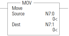
MOV - Move
The MOV instruction is used to move data from the source to the destination. As long as the rung remains true, the instruction moves the data each scan.
Using the MOV Instruction
When using the MOV instruction, observe the following:
Source and Destination can be different data sizes. The source is converted to the destination size when the instruction executes. If the signed value of the Source does not fit in the Destination, the overflow is handled as follows
– If the Math Overflow Selection Bit is clear, a saturated result is stored in the Destination. If the Source is positive, the Destination is 32767 (word). If the result is negative, the Destination is -32768 (word).
– If the Math Overflow Selection Bit is set, the unsigned truncated value of the Source is stored in the Destination.
Source can be a constant or an address.
Valid constants are -32,768…32,767 (word) and-2,147,483,648…2,147,483,647 (long word).
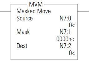
MVM - Masked Move
The MVM instruction is used to move data from the source to the destination, allowing portions of the destination to be masked.
Using the MVM Instruction
When using the MVM instruction, observe the following:
Source, Mask, and Destination must be of the same data size (i.e. all words or all long words).
To mask data, set the mask bit to zero; to pass data, set the mask bit to one. The mask can be a constant value, or you can vary the mask by assigning a direct address.
Section-G :File Instructions
The file instructions perform operations on file data.
Instruction
CPW – Copy Word
COP – Copy File
FLL – Fill File
BSL – Bit Shift Left
BSR – Bit Shift Right
Used To:
Copy words of data from one location to another.
Copy a range of data from one file location to another
Load a file with a program constant or a value from an element address
Load and unload data into a bit array one bit at a time
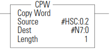
CPW - Copy Word
The CPW instruction copies words of data, in ascending order, from one location (Source) to another (Destination). Although similar to the File Copy (COP) instruction, the CPW instruction allows different source and destination parameters.
Examples include:
integer to long word
long word to floating point
long word to integer
integer to PTOX function file
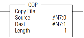
COP - Copy File
The COP instruction copies blocks of data from one location into another.
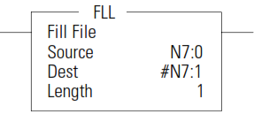
FLL - Fill File
The FLL instruction loads elements of a file with either a constant or an address data value for a given length. The following figure shows how file instruction data is manipulated. The instruction fills the words of a file with a source value. It uses no status bits. If you need an enable bit, program a parallel output that uses a storage address.
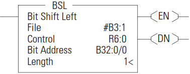
BSL - Bit Shift Left
The BSL instruction loads data into a bit array on a false-to-true rung transition, one bit at a time. The data is shifted left through the array, then unloaded, one bit at a time.
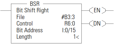
BSR - Bit Shift Right
The BSR instruction loads data into a bit array on a false-to-true rung transition, one bit at a time. The data is shifted right through the array, then unloaded, one bit at a time
Section-H :Program Control Instructions
Use these instructions to change the order in which the processor scans a ladder program. Typically these instructions are used to minimize scan time, create a more efficient program, and troubleshoot a ladder program.
Instruction
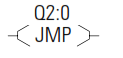
JMP – Jump to Label
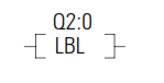
LBL – Label
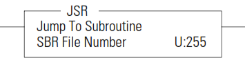
JSR – Jump to Subroutine
END – Program End
Used To:
Jump forward/backward to a corresponding label instruction
Jump forward/backward to a corresponding label instruction
Jump to a designated subroutine and return
End a program or subroutine
JMP - Jump to Label
The JMP instruction causes the controller to change the order of ladder execution. Jumps cause program execution to go to the rung marked LBL label number. Jumps can be forward or backward in ladder logic within the same program file. Multiple JMP instructions may cause execution to proceed to the same label.
The immediate data range for the label is from 0…999. The label is local to a program file.
LBL - Label
The LBL instruction is used in conjunction with a jump (JMP) instruction to change the order of ladder execution. Jumps cause program execution to go to the rung marked LBL label number.
The immediate data range for the label is from 0…999. The label is local to a program file.
JSR - Jump to
Subroutine
The JSR instruction causes the controller to start executing a separate subroutine file within a ladder program. JSR moves program execution to the designated subroutine (SBR file number). After executing the SBR, control proceeds to the instruction following the JSR instruction.
The immediate data range for the JSR file is from 3…255.
END - Program End
The END instruction must appear at the end of every ladder program. For the main program file (file 2), this instruction ends the program scan. For a subroutine, interrupt, or user fault file, the END instruction causes a return from subroutine.
Section-I :Process Control Instruction
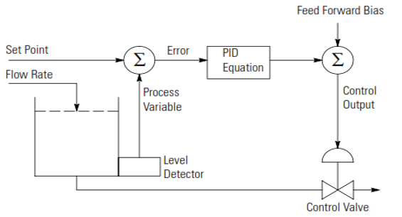
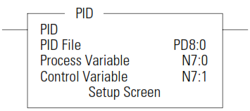
The PID instruction is an output instruction that controls physical properties such as temperature, pressure, liquid level, or flow rate using process loops.
The PID Concept
The PID instruction normally controls a closed loop using inputs from an analog input module and providing an output to an analog output module. For temperature control, you can convert the analog output to a time proportioning on/off output for driving a heater or cooling unit.
The PID instruction can be operated in the timed mode or the Selectable Time Interrupt (STI mode). In the timed mode, the instruction updates its output periodically at a user-selectable rate. In the STI mode, the instruction should be placed in an STI interrupt subroutine. It then updates its output every time the STI subroutine is scanned. The STI time interval and the PID loop update rate must be the same in order for the equation to execute properly.
A flow rate/fluid level example is shown below.
PID - Proportional
Integral Derivative
It is recommended that you place the PID instruction on a rung without any conditional logic. If conditional logic exists, the Control Variable output remains at its last value, and the CVP CV% term and integral term are both cleared when the rung is false.
Section-J :Recipe and Data Logging
This chapter describes how to use the Recipe and Data Logging functions.
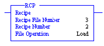
RCP - Recipe
The RCP file allows you to save custom lists of data associated with a recipe. Using these files along with the RCP instruction lets you transfer a data set between the recipe database and a set of user-specified locations in the controller file system.
The recipe data is stored in Data Log Queue memory.
The following reasons may help you choose which type of memory to use:
All the recipe data is stored into the controller’s memory module. Because the recipe data is stored in Data Log Queue memory, it does not consume user program space.
If you are not using the data logging function, it allows you more memory (up to 64K bytes) for RCP files. You can use the Data Log Queue for data logging and recipe data, but the total cannot exceed 128K bytes.
The RCP instruction uses the following parameters:
Recipe File Number – this is the file number that identifies the custom list of addresses associated with a recipe.
Recipe Number – specifies the number of the recipe to use. If the recipe number is invalid, a user fault (code 0042) is generated
File Operation – identifies whether the operation is a Load from the database or a Store to the database.
When executed on a True rung, the RCP instruction transfers data between the recipe database and the specified data locations.
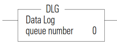
DLG - Data Log
Instruction
The DLG instruction triggers the saving of a record. The DLG instruction has one operand:
Queue Number – Specifies which data log queue captures a record
The DLG instruction only captures data on a false-to-true rung transition. The DLG rung must be reset (scanned false) before it will capture data again. Never place the DLG instruction alone on a rung.
Data Log Status File
There is a Data Log Status (DLS) file element for each Data Log Queue.
The DLS file does not exist until a data log queue has been configured.
The Data Log Status file has 3-word elements. Word 0 is addressable by bit only through ladder logic. Words 1 and 2 are addressable by word and/or bit through ladder logic.
The number of DLS file elements depends upon the number of queues
specified in the application.
Section-K :Communications Instruction
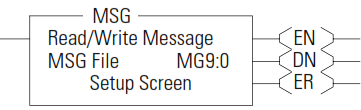
This chapter contains information about the Message (MSG) communication instructions.
MSG - Message
Any preceding logic on the message rung must be solved true before the message instruction can be processed.
the MSG rung is true, and MG9:0 is not already processing a message; then MG9:0 is processed. If one of the four buffers is available, the message and its associated data are processed immediately.
Section-L :LCD - LCD Information
This chapter describes how to use the LCD functions.
LCD Overview
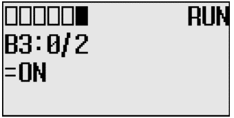
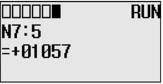
Through the embedded LCD, your MicroLogix 1400 lets you monitor bit, integer and long integer data within the controller, and optionally modify that data, to interact with your control program. Similarly to the optional 1764-DAT for the MicroLogix 1500 controllers, the embedded MicroLogix 1400 LCD allows users access to 256 bits, 256 integers and 256 long integers, each of which can be individually protected. If you need to know the speed of a conveyor, the status of a remote sensor, or how close your process is running relative to its optimal temperature, you can just monitor your LCD.
You can manually start an operation, change a timing sequence, or make adjustments to a counter, and use the LCD to simulate pushbuttons or numeric entry devices. By simply moving or copying data in and out of the bit and integer files, you now can monitor and modify the parameters that your controller uses.
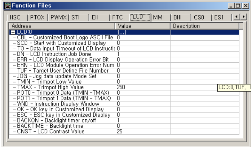
LCD Function File
Within the RSLogix 500/RSLogix Micro Function File Folder, you see a LCD Function File. This file provides access to LCD and Trimpot configuration data, and also allows the control program access to all information pertaining to LCD screen, keypad, Trimpot.
The LCD Function File contains status information and control configurations for LCD, Trimpot, and keypad, such as:
• Information about whether to use a customized display at power-up • Keypad key-in mode and timeout settings • Bit, Integer and Long Integer data files to monitor • Current Trimpot values and Trimpot value range settings
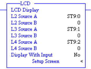
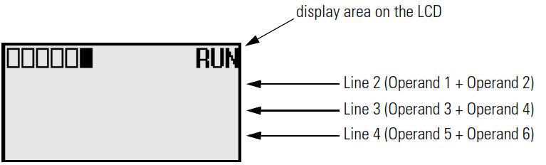
LCD - LCD Instruction
The LCD instruction is used to display string or number, get value with keypad.
If Display With Input is set to 0 and the address mode of L2 Source A, L2 Source B, L3 Source A, L3 Source B, L4 Source A, L4 Source B are immediate mode, these value shall be 0.