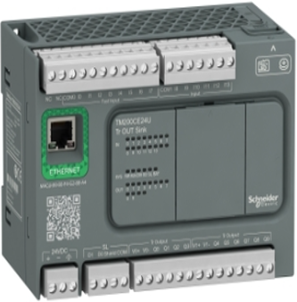
Section- 1 Schneider PLC TM200CE24U
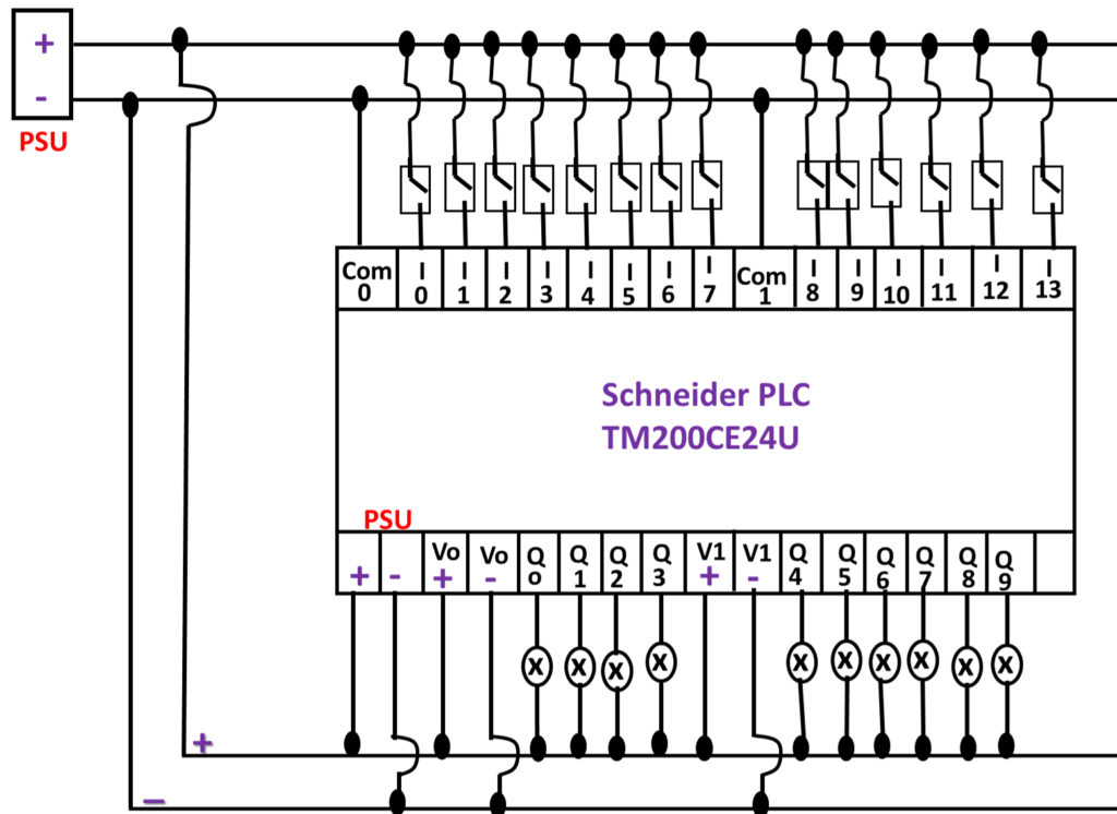
INPUT/OUTPUT WIRING And Overview..
Schneider PLC INPUT/OUTPUT WIRING.
Schneider PLC TM200CE24U
Schneider PLC Input / Output Wiring.
Section- 2 Schneider TM200 PLC Communication | Program Download to Schneider PLC
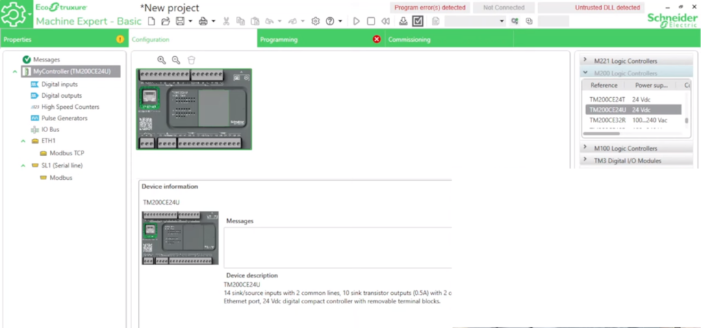
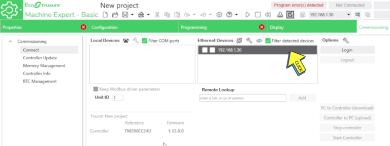
How to communicate and download program in Schneider PLC?
Step 1 –
Open “Eco Struxure Machine Expert”
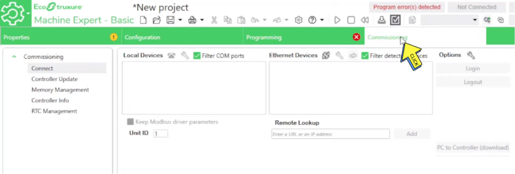
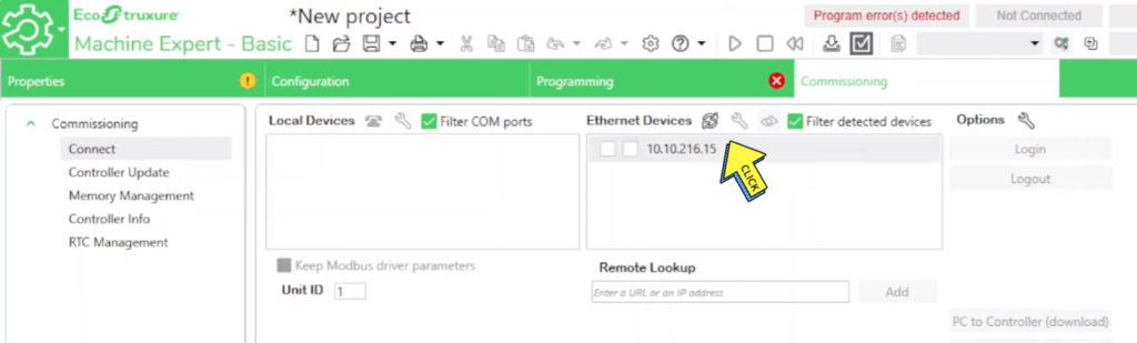
Step 2 –
Click on “Commissioning“
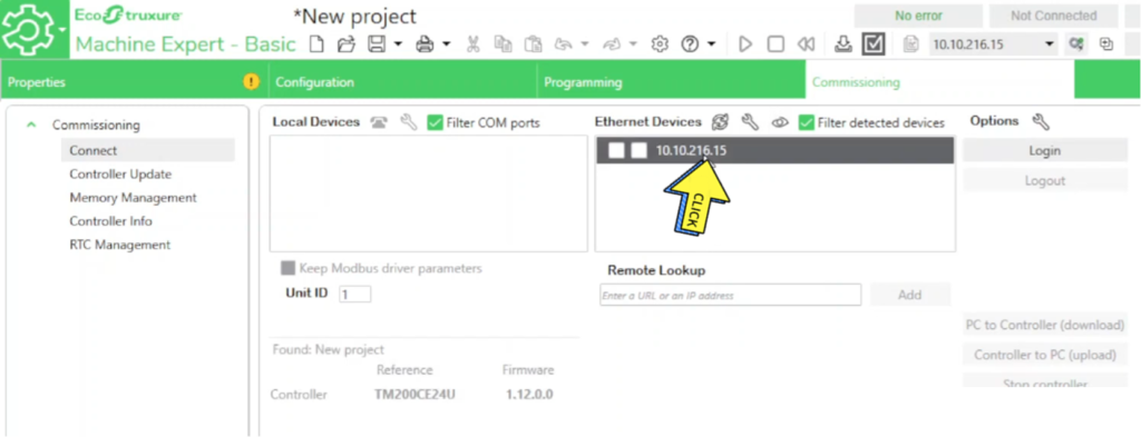
Step 3 –
Search “Automatic PLC “
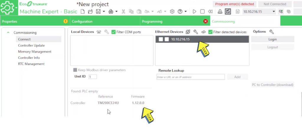
Step 4-
Select on “IP Address” and
Show on “Controller, Firmware”
Firmware: To create the project, it will be created only in 1.12.0.0 Level
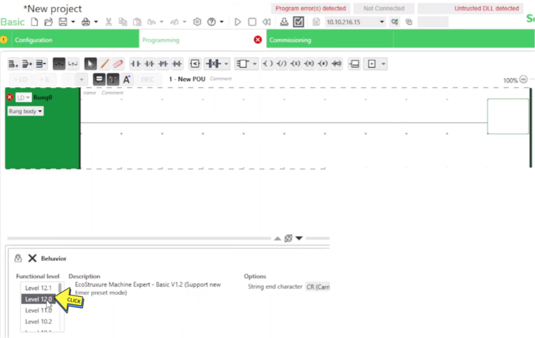
Step 5-
Select on “Programming Level 12.0”
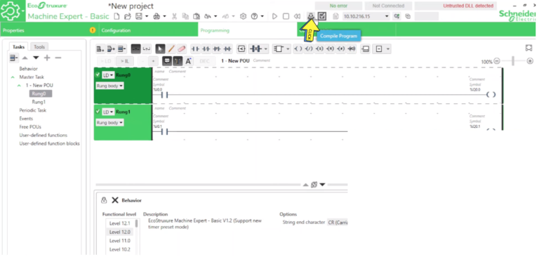
Step 6-
Click on “Compile Program”
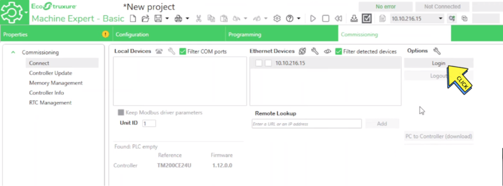
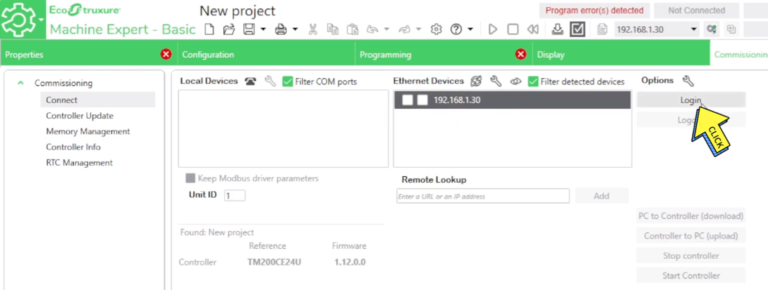
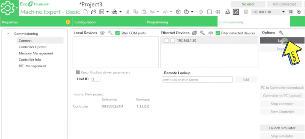
Step 7-
Click on “Login button”
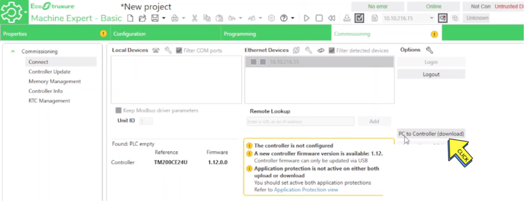
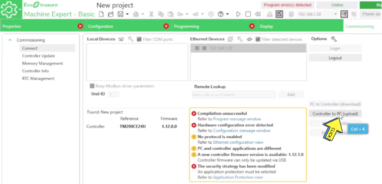
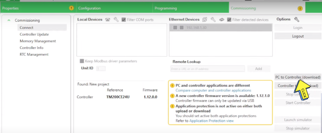
Step 8-
Click on “PC to C0ntroller (Download)“d
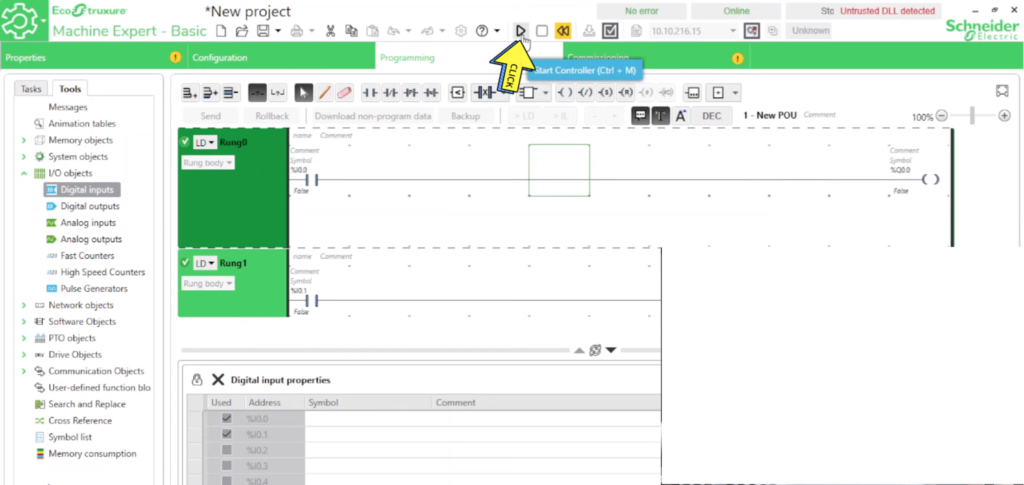
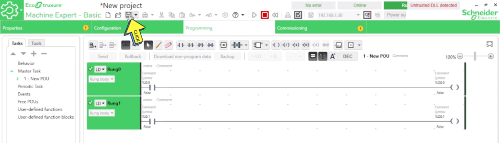
Step 9-
Click on “Start Controller button”
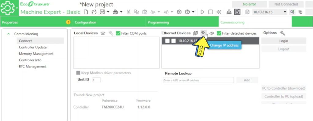
Section- 3 How to Find and Change or Set the IP Address of a TM200 Schneider PLC?
How to Change the IP Address of a TM200 Schneider PLC?
Step 1-
Click on “IP Address”
Step 2 –
Click on “Change IP Address”
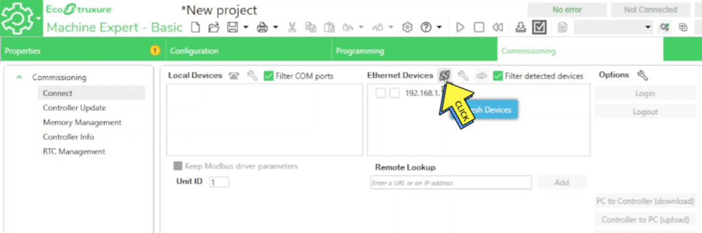
Step 3 –
Enter Your “IP Address”
Step 4 –
Click on “Refresh Devices”
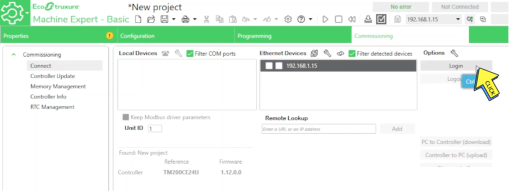
Step 5 –
Click on “Login button”
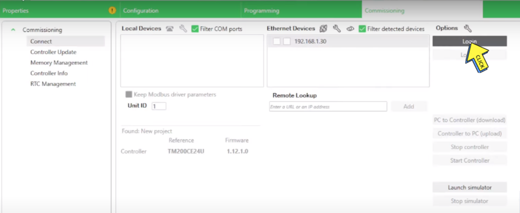
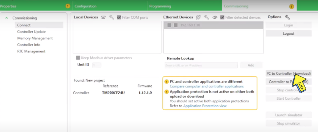
Section- 4 HOW TO UPLOAD PROGRAM FROM SCHNEIDER TM200 PLC TO PC? | Schneider PLC program backup procedure.
How to Upload Program From Schneider TM200 PLC To PC.
Step 1 –
Open “EcoStruxure Machine Expert – Basic”
Step 2 –
Click on “Commissioning”
Step 3-
Search on “IP Address”
Step 4-
The laptop IP must match the first 3 blocks of the controller IP.
Step 5-
The laptop IP must match the first 3 blocks of the controller IP.
Step 6-
Click on “Login button”
Step 7-
Click on “Controller TO PC (Upload)”
Step 8-
Click on “Save button”
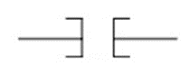
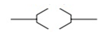
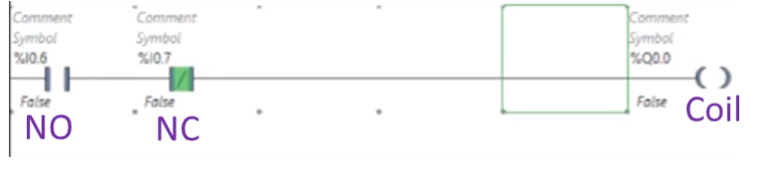
Section- 5 What is the NO and NC contact and output coil in a ladder logic diagram in Schneider TM200 PLC?
What is NO and NC contact in PLC?
NO – Normally Open – NO contact is normally open and becomes closed once its coil is energized
NC – Normally Closed – NC contact is normally closed and becomes open once its coil is energized.
Outputs from a PLC are referred to as coils on a ladder diagram. A coil may represent a motor, light, pump, counter, timer, relay, etc.
Example:-
Section- 6 Timer Instructions.
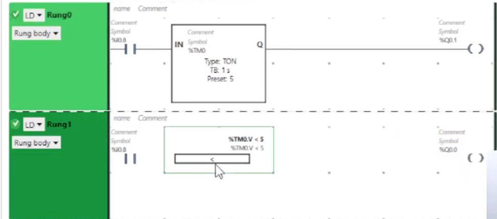
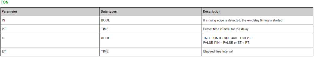
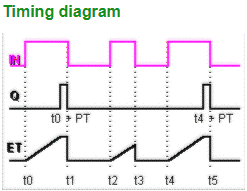
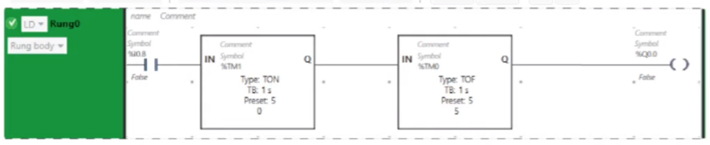
TON - ON Delay Timer
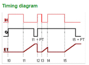
TON Timer:- If the input IN changes from FALSE to TRUE, switching on is delayed for the time interval set at the input PT. After the delay time set at PT has elapsed, Q is set to TRUE. The already elapsed time is indicated at ET.
NOTE:-
If the value applied at PT (Preset Time) is 0 or lower than the system’s cycle time and a rising edge occurs at input IN, output Q is not set to TRUE until the next cycle
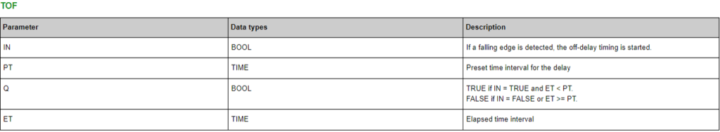
TOF - OFF Delay Timer
TOF Timer:-
If the input IN changes from TRUE to FALSE, switching off is delayed for the time interval set at the input PT. After the delay time set at PT has elapsed, Q is set to FALSE.
Note:-
If the value applied at PT (Preset Time) is 0 or lower than the system’s cycle time and a falling edge occurs at input IN, output Q is not reset to FALSE until the next cycle.
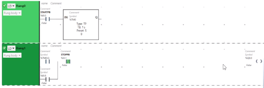
Holding & Breaking Concept in PLC using Pulse Timer
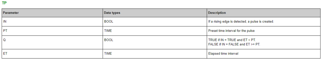
TP Timer:-
If the input IN changes from FALSE to TRUE, a pulse is created at output Q for the time interval set at the input PT. The elapsed time while Q=TRUE is output at ET. If IN becomes TRUE for a second time before the time set at PT has elapsed, Q remains unchanged.
NOTE:-
If you want to use the standard function block TP in your code worksheet, you have to select the data type ‘TP’ for the function block instance in the local variables worksheet. Accordingly, the data types ‘BOOL’ and ‘TIME’ must be used instead of ‘SAFEBOOL’ and ‘SAFETIME’.
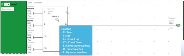
Section- 7 Counter Instructions.
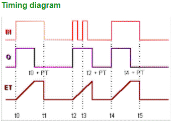
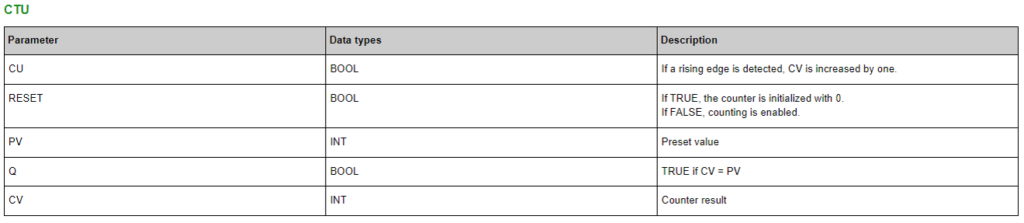
Count up Counter (CTU)
Count up (CTU):-
In case of a rising edge at the input CU and RESET = FALSE, CV is increased by one. When CV reaches the value specified at PV, Q is set to TRUE and the function block stops counting. If RESET = TRUE, the counter is initialized with 0. To enable the counting process, RESET must be FALSE.
NOTE: If you want to use the standard function block CTU in your code worksheet, you have to select the data type ‘CTU’ for the function block instance in the local variables worksheet. Accordingly, the data types ‘BOOL’ and ‘INT’ must be used instead of ‘SAFEBOOL’ and ‘SAFEINT’.
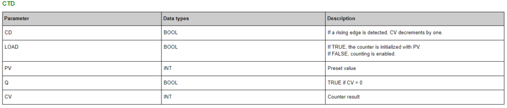
Count Down Counter (CTD)
Count Down (CTD):-
In case of a rising edge at the input CD and LOAD = FALSE, CV decrements by one. When CV reaches the value 0, Q is set to TRUE and the function block stops counting. If LOAD = TRUE, the counter is initialized by the value of the input PV. To enable the counting process, the input LOAD must be FALSE.
NOTE: If you want to use the standard function block CTD in your code worksheet, you have to select the data type ‘CTD’ for the function block instance in the local variables worksheet. Accordingly, the data types ‘BOOL’ and ‘INT’ must be used instead of ‘SAFEBOOL’ and ‘SAFEINT’.
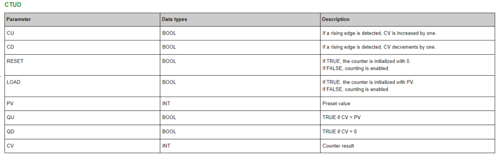
What is count up and count down counter in PLC?
Count UP/ Down (CTUD):-
. In case of a rising edge at the input CU, CV is increased by one. In case of a rising edge at the input CD, CV decrements by one. If CV = PV, QU is set to TRUE. If CV = 0, QD is set to TRUE. If RESET = TRUE, the counter is initialized with 0. If LOAD = TRUE, the counter is initialized with PV. To enable the counting process, the inputs RESET and LOAD must be FALSE.
NOTE: If you want to use the standard function block CTUD in your code worksheet, you have to select the data type ‘CTUD’ for the function block instance in the local variables worksheet. Accordingly, the data types ‘BOOL’ and ‘INT’ must be used instead of ‘SAFEBOOL’ and ‘SAFEINT’.
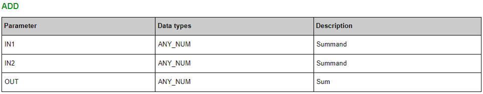
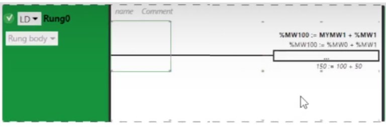
Addition:- This arithmetic function realizes an addition of the operands connected to the input parameters. It is available as standard function ADD.,
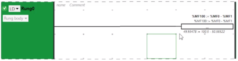
Subtraction Operation
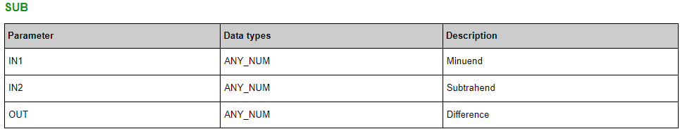
Subtraction:- This arithmetic function subtracts IN2 from IN1. The function is available as standard function SUB.
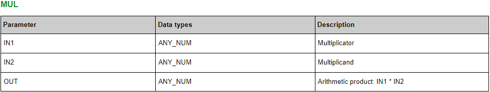
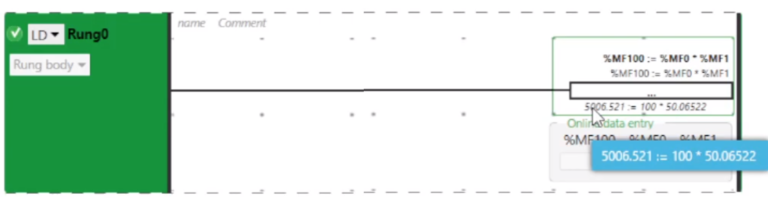
Multiplication Operation
Multiplication:- This arithmetic function multiplies the operands connected to the input parameters and outputs the product.
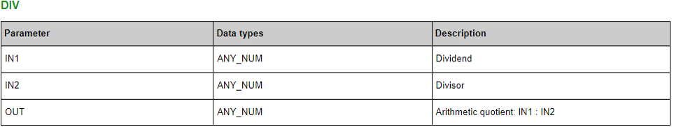
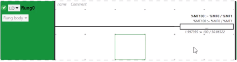
Division Operation
Division:- This arithmetic function divides the dividend connected to IN1 by the operand connected to IN2 and outputs the quotient.
NOTE: Division by zero is not allowed and results in an error. As a result, the Safety Logic Controller enters the Stop state.
NOTE: As the output value must be of an Integer data type, a possible rest of the division is deleted.
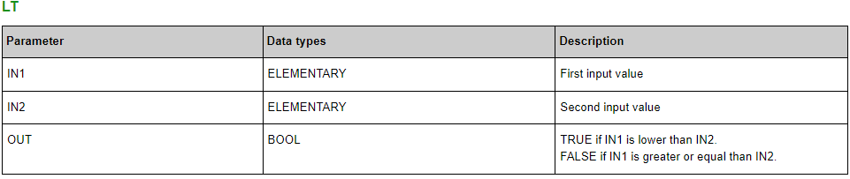
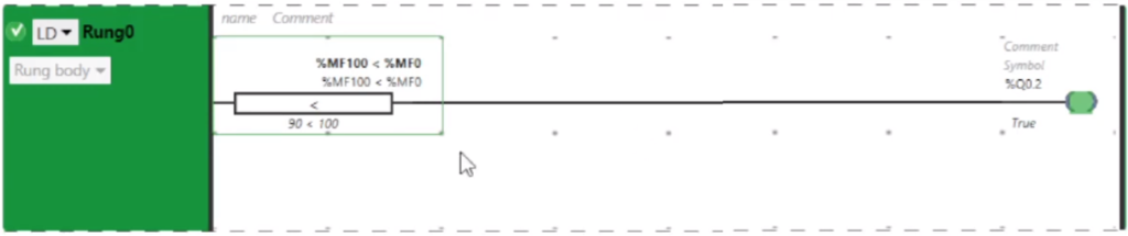
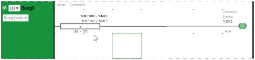
Less Then Operation
Less then:- This comparison function compares the operands connected to the input parameters in regard to less. Comparison proceeds from left to right.
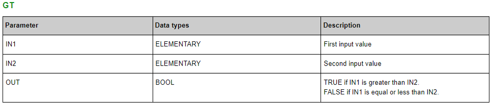
Greater Then Operation
Greater Then:- This comparison function compares the operands connected to the input parameters in regard to greater. Comparison proceeds from left to right.
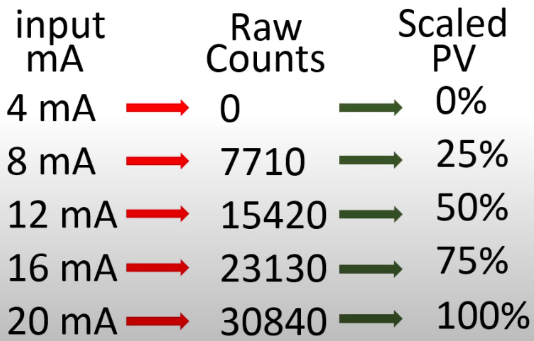
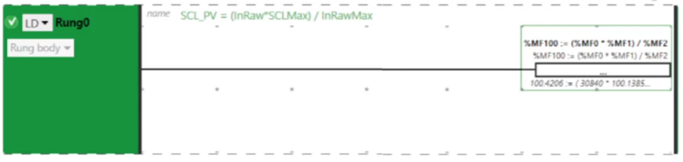
Section- 9 :- How to scale Analog Input 4-20 mA signal?
When the analog input signal enters the PLC you will have to scale it in your PLC program.
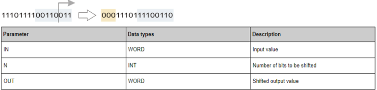
This standard bit-string function performs a bitwise right shift operation on the standard WORD operand connected to the IN input. N specifies the number of bits to be shifted.
The following rules apply:
The “empty bit positions” resulting from the shifting operation are filled with zeros.
When shifting with N < 0, the function delivers the output value 0 because the N parameter is considered as an unsigned integer value.
Example: bitwise right shifting with N = 3 bits.
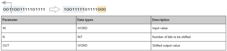
SHL: Shift bit pattern left
This standard bit-string function performs a bitwise left shift operation on the standard WORD operand connected to the IN input. N specifies the number of bits to be shifted.
The following rules apply:
The “empty bit positions” resulting from the shifting operation are filled with zeros.
When shifting with N < 0, the function delivers the output value 0 because the N parameter is considered as an unsigned integer value.
Example: bitwise left shifting with N = 3 bits.
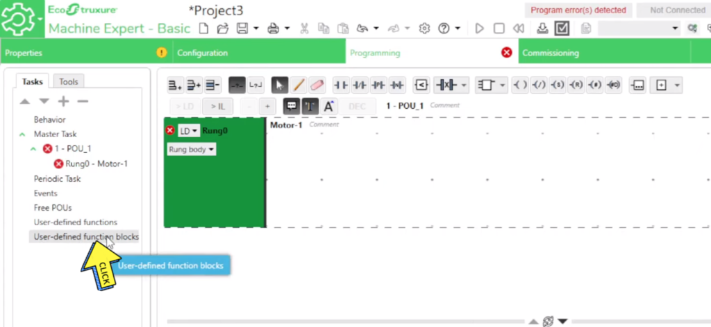
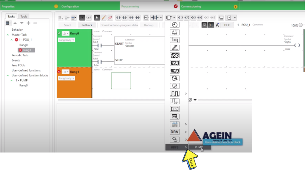
Section- 11 :- How to Create Re-usable Function Block in Machine Expert Basic?
(1st Method ) Create User-defined Function Block.
Step-1
Right Click on “User-defined function block”
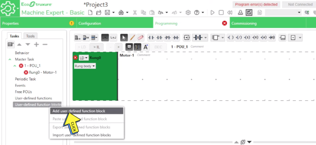
Step-2
Click on “Add user-defined function block”
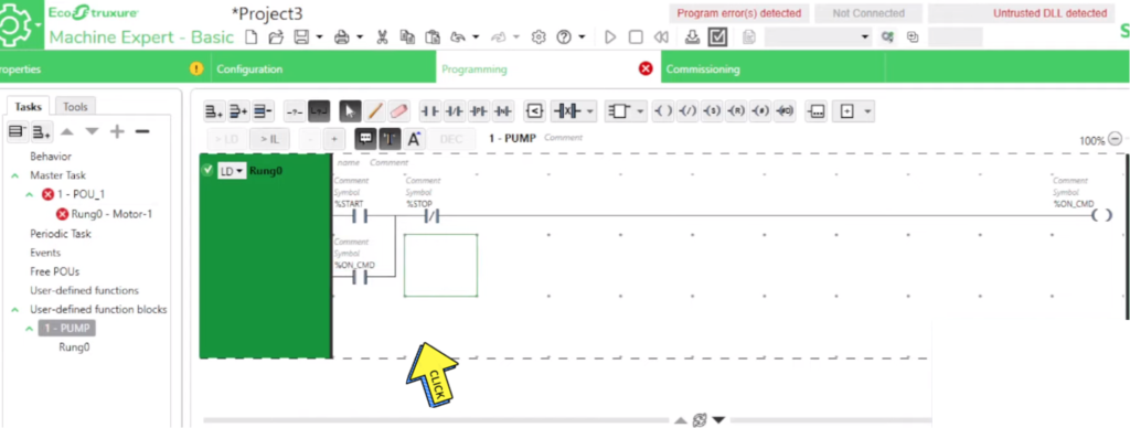
Step-3
Type your “Program”
Step-4
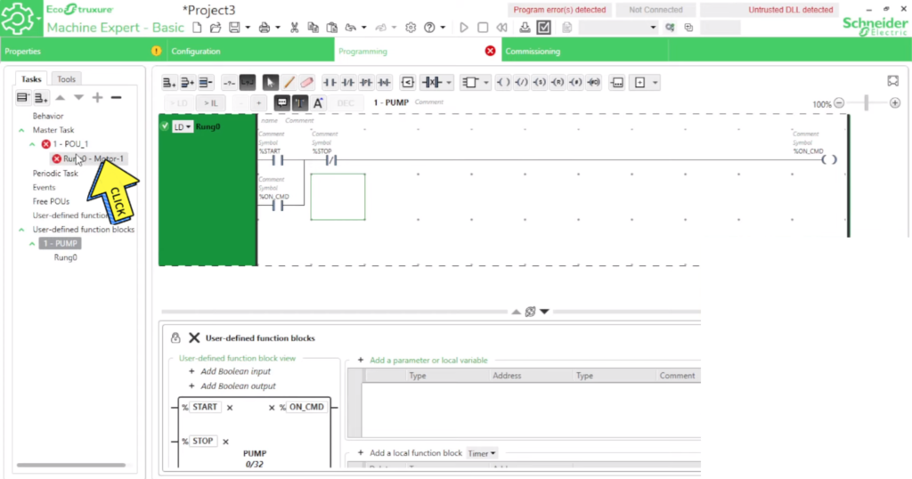
Click on “Rung0”
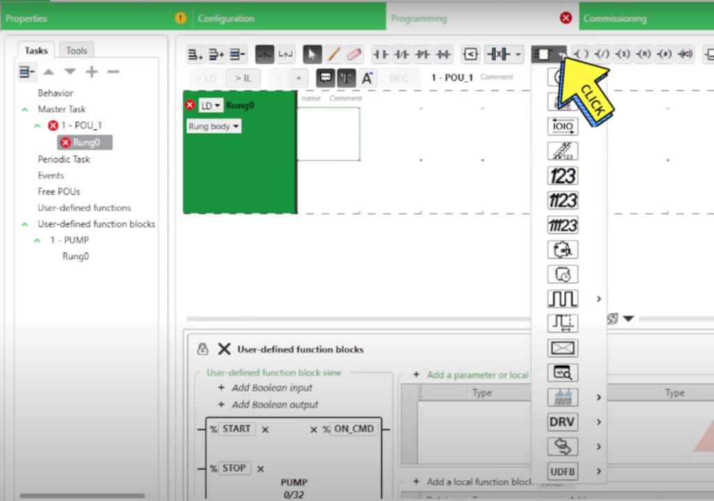
Step-5
Click on “Function Block”
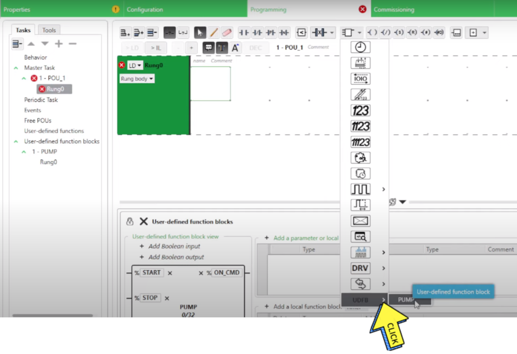
Step-6
Click on “User & UDFB”
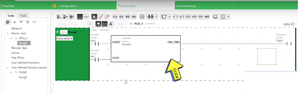
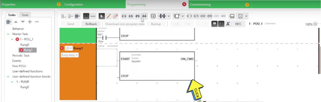
Step-7
Show on Block “Start, Stop, ON_CMD”
Step-8
Click on “Login button”
Step-9
Click on “PC to Controller (download)”
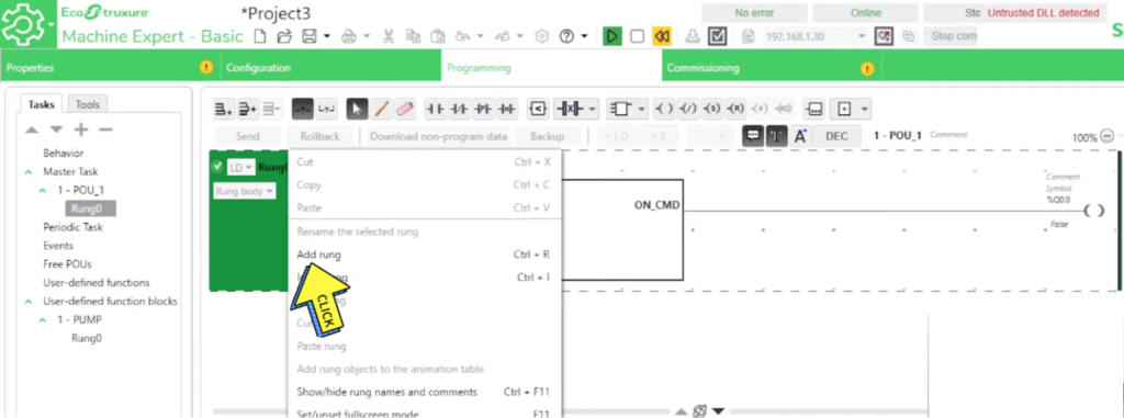
2nd (Method) How to Create Re-usable Function Block
Step-1
Click on “Add Rung”
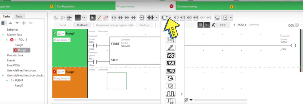
Step-2
Click on “Function Block”
Step-3
Select on “UDFD & PUMP”
Step-4
Program “Re-usable”
Step-5
Compete “Re-usable Program”
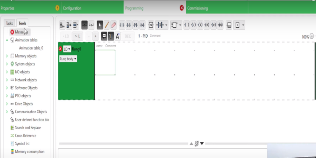
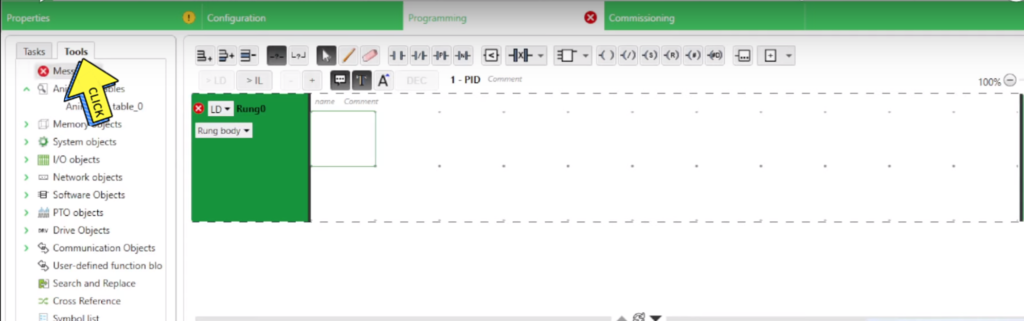
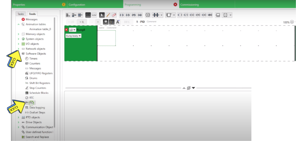
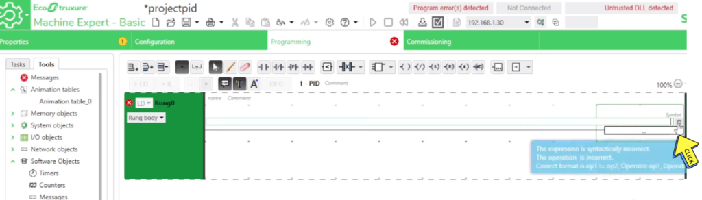
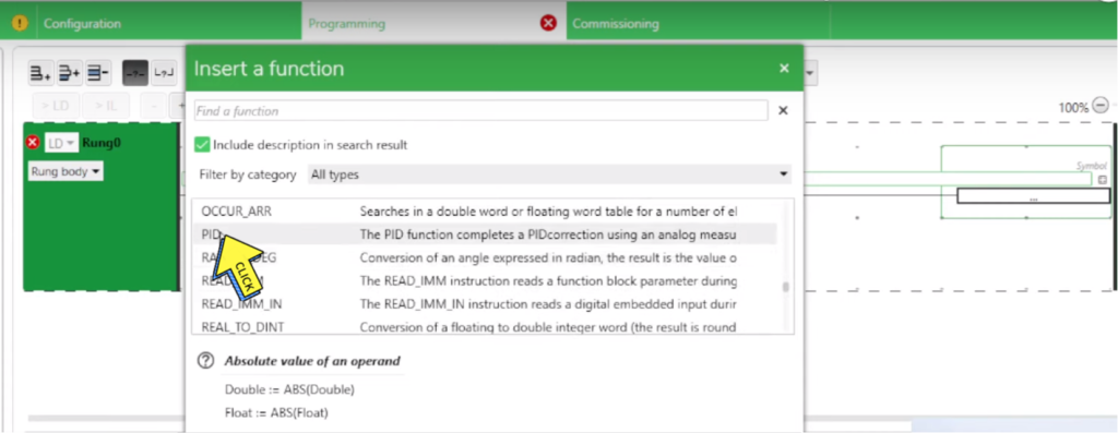
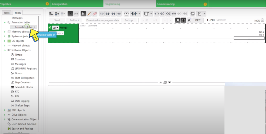
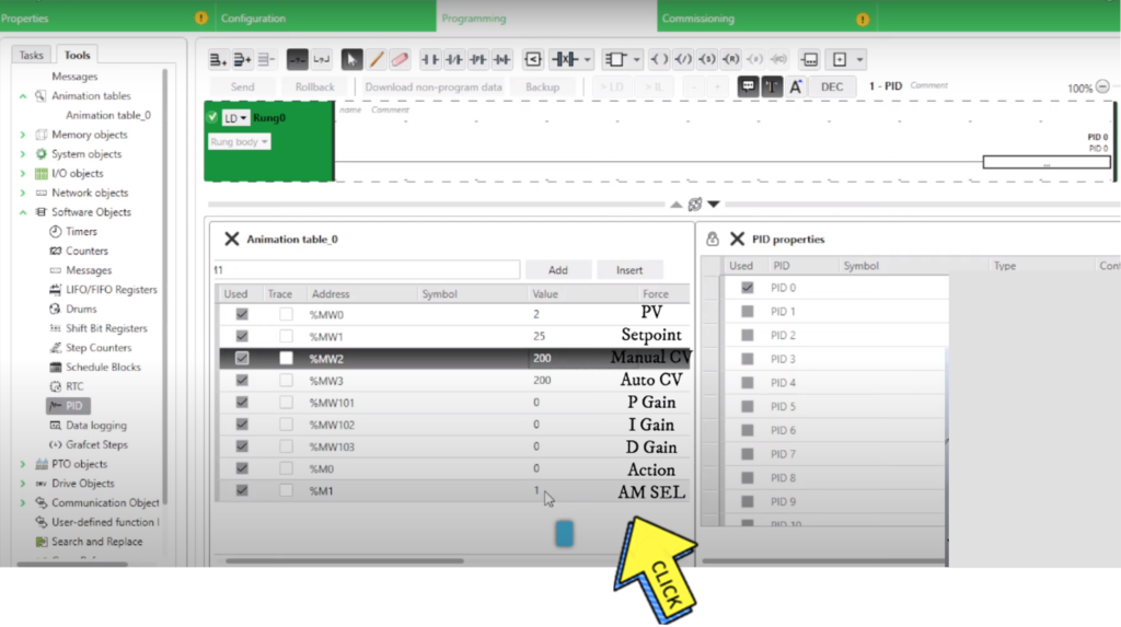
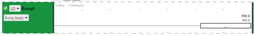
Section- 12 :- What is PID and how does it work? PID Function Block in Machine Expert Basic
What is PID and how does it work?
Step-1
Open “Machine Expert Basic”
Step-2
Click on ” Tools”
Step-3
Click on “Software Objects” And
Select “PID”
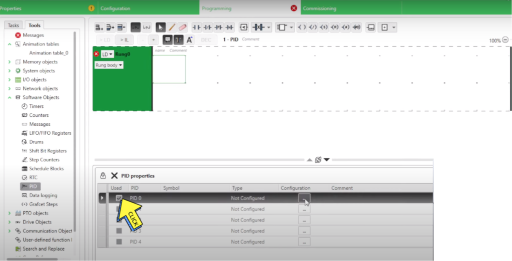
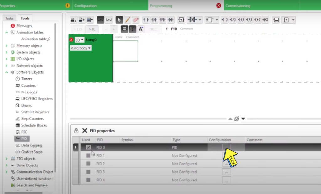
Step- 4
Select on “PID 0”
Step- 5
Click on “PID”
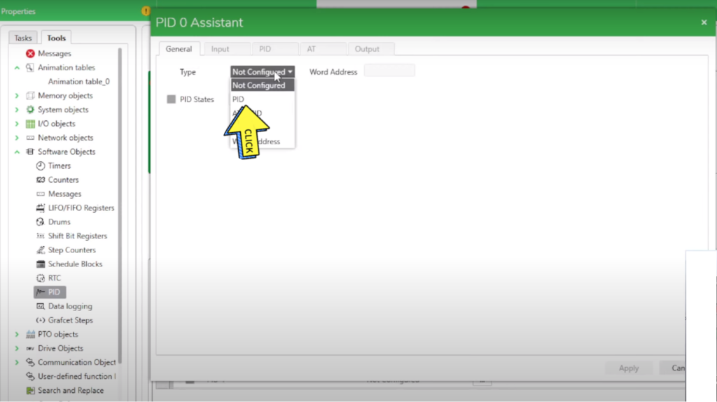
Step- 6
Show on “PID0 Assistant”
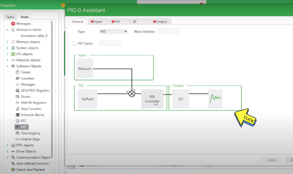
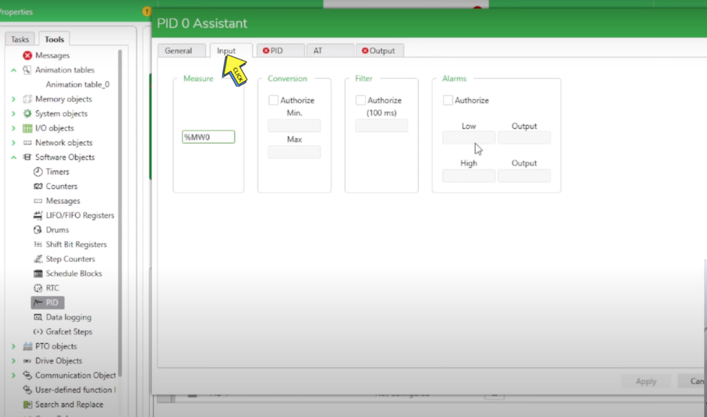
Step- 7
Select “Input”
Fill the “Measure”
Step – 8
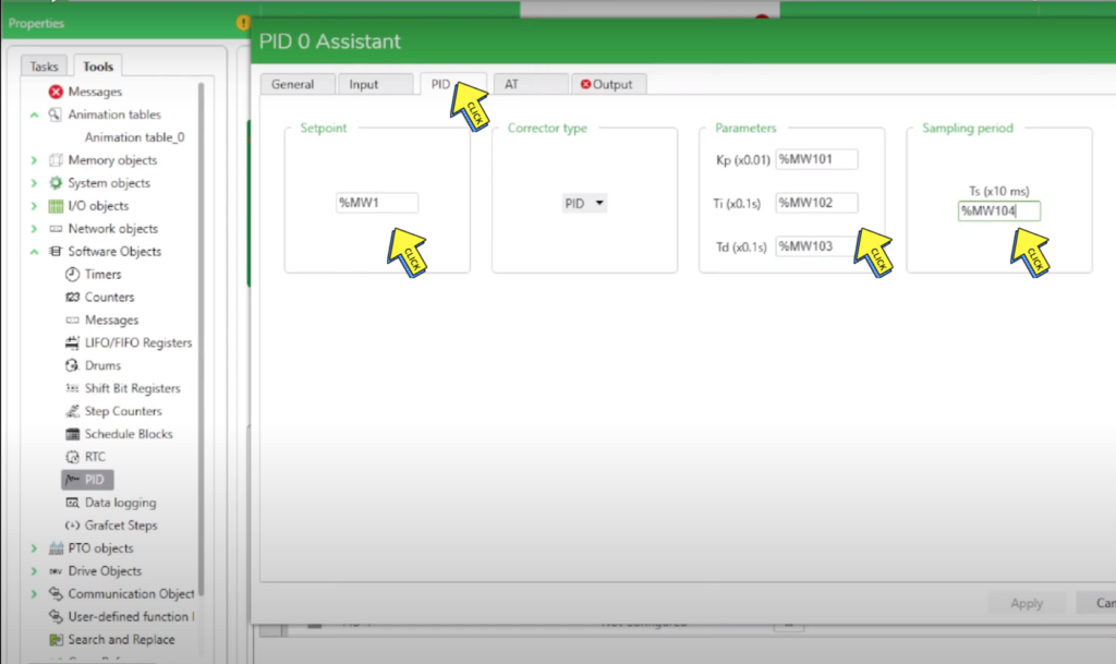
Select on “PID”
Fill the “Setpoint, Corrector type, Parameters, Sampling period”
Step – 9
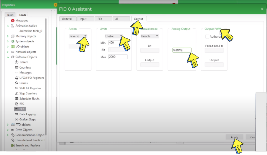
Select on “Output”
Fill the “Action, Limits, Manual mode, Analog Output, Output PWM”