Section-1: Introduction of Siemens S7-1200 PLC Hardware overview and wiring
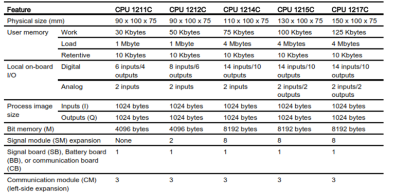
Comparing the CPU models
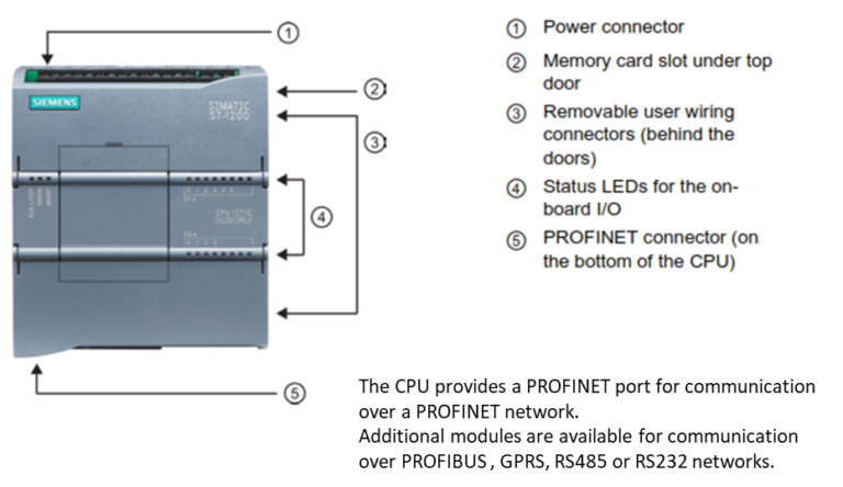
Siemens S7-1200 PLC Hardware overview
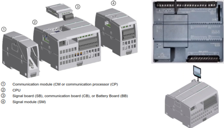
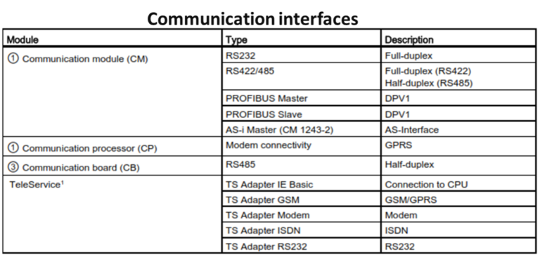
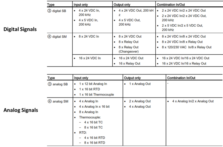
Signals Modules/Boards
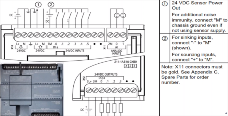
CPU 1211C DC/DC/DC (6ES7 211-1AE40-OXBO
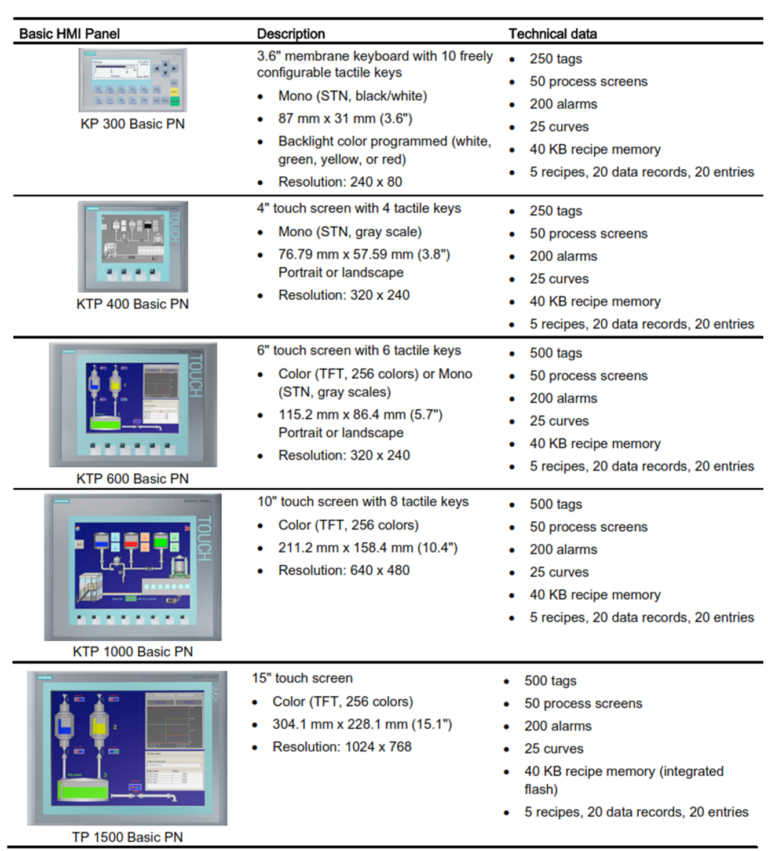
Basic HMI panels
The SIMATIC HMI Basic Panels provide touch-screen devices for basic operator control and monitoring tasks. All panels have a protection rating for IP65 and have CE, UL, cULus, and NEMA 4x certification.
Section-2: TIA Portal Complete Software Overview / Creating New Project.
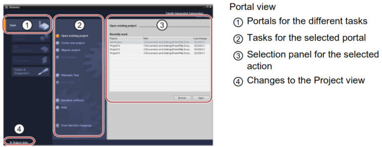
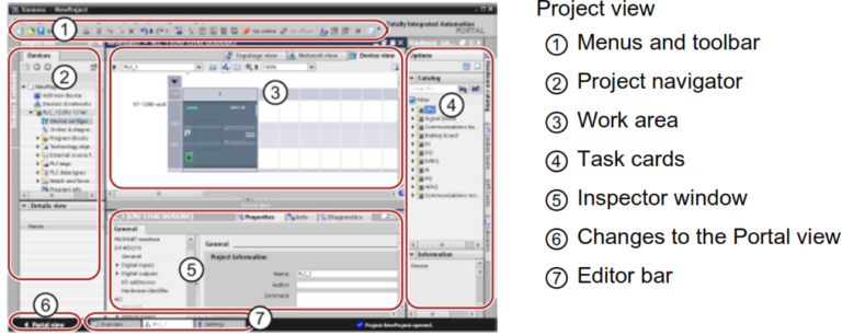
7 provides a user-friendly environment to develop controller logic, configure HMI visualization, and setup network communication. To help increase your productivity, STEP 7 provides two different views of the project: a task-oriented set of portals that are organized on the functionality of the tools (Portal view), or a project-oriented view of the elements within the project (Project view). Choose which view helps you work most efficiently. With a single click, you can toggle between the Portal view and the Project view.
Using blocks to structure your program
Organization block (OB)
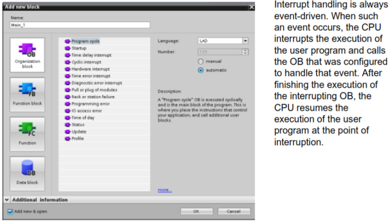
Organization blocks provide structure for your program. They serve as the interface between the operating system and the user program. OBs are event driven. An event, such as a diagnostic interrupt or a time interval, causes the CPU to execute an OB. Some OBs have predefined start events and behavior.
The program cycle OB contains your main program. You can include more than one program cycle OB in your user program. During RUN mode, the program cycle OBs execute at the lowest priority level and can be interrupted by all other event types. The startup OB does not interrupt the program cycle OB because the CPU executes the startup OB before going to RUN mode.
After finishing the processing of the program cycle OBs, the CPU immediately executes the program cycle OBs again. This cyclic processing is the “normal” type of processing used forprogrammable logic controllers. For many applications, the entire user program is located in a single program cycle OB.
You can create other OBs to perform specific functions, such as for handling interrupts and errors, or for executing specific program code at specific time intervals. These OBs interrupt the execution of the program cycle OBs.
Function block (FB)
A function block (FB) is a code block that uses an instance data block for its parameters and static data. FBs have variable memory that is located in a data block (DB), or “instance” DB. The instance DB provides a block of memory that is associated with that instance (or call) of the FB and stores data after the FB finishes. You can associate different instance DBs with different calls of the FB. The instance DBs allow you to use one generic FB to control multiple devices. You structure your program by having one code block make a call to an FB and an instance DB. The CPU then executes the program code in that FB, and stores the block parameters and the static local data in the instance DB. When the execution of the FB finishes, the CPU returns to the code block that called the FB. The instance DB retains the values for that instance of the FB. These values are available to subsequent calls to the function block either in the same scan cycle or other scan cycles.
Assigning the start value in the instance DB
The instance DB stores both a default value and a start value for each parameter. The start value provides the value to be used when the FB is executed. The start value can then be modified during the execution of your user program.
The FB interface also provides a “Default value” column that allows you to assign a new start value for the parameter as you are writing the program code. This default value in the FB is then transferred to the start value in the associated instance DB. If you do not assign a new start value for a parameter in the FB interface, the default value from instance DB is copied to start value.
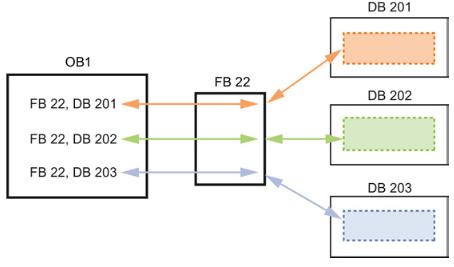
Using a single FB with DBs
The following figure shows an OB that calls one FB three times, using a different data block for each call. This structure allows one generic FB to control several similar devices, such as motors, by assigning a different instance data block for each call for the different devices. Each instance DB stores the data (such as speed, ramp-up time, and total operating time) for an individual device.
Function (FC)
A function (FC) is a code block that typically performs a specific operation on a set of input values. The FC stores the results of this operation in memory locations. For example, use FCs to perform standard and reusable operations (such as for mathematical calculations) or technological functions (such as for individual controls using bit logic operations). An FC can also be called several times at different points in a program. This reuse simplifies the programming of frequently recurring tasks.
An FC does not have an associated instance data block (DB). The FC uses the local data stack for the temporary data used to calculate the operation. The temporary data is not saved. To store data permanently, assign the output value to a global memory location, such as M memory or to a global DB.
Data block (DB)
You create data blocks (DB) in your user program to store data for the code blocks. All of the program blocks in the user program can access the data in a global DB, but an instance DB stores data for a specific function block (FB).
The data stored in a DB is not deleted when the execution of the associated code block comes to an end. There are two types of DBs:
● A global DB stores data for the code blocks in your program. Any OB, FB, or FC can access the data in a global DB.
● An instance DB stores the data for a specific FB. The structure of the data in an instance DB reflects the parameters (Input, Output, and InOut) and the static data for the FB. (The Temp memory for the FB is not stored in the instance DB.)
Note Although the instance DB reflects the data for a specific FB, any code block can access the data in an instance DB.
Creating reusable code blocks
You can store objects you want to reuse in libraries. For each project, there is a project library that is connected to the project. In addition to the project library, you can create any number of global libraries that can be used over several projects. Since the libraries are compatible with each other, library elements can be copied and moved from one library to another.
Libraries are used, for example, to create templates for blocks that you first paste into the project library and then further develop there. Finally, you copy the blocks from the project library to a global library. You make the global library available to other colleagues working on your project. They use the blocks and further adapt them to their individual requirements, where necessary.
Section-3: Programming language
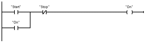
● LAD (ladder logic) is a graphical programming language. The representation is based on circuit diagrams.
● FBD (Function Block Diagram) is a programming language that is based on the graphical logic symbols used in Boolean algebra.
● SCL (structured control language) is a text-based, high-level programming language.
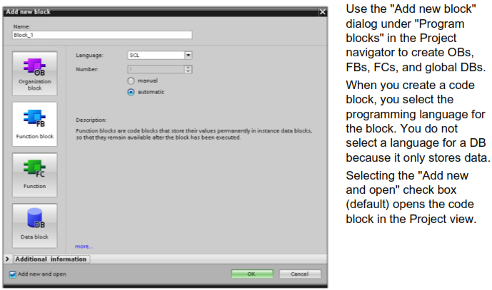
When you create a code block, you select the programming language to be used by that block.
Your user program can utilize code blocks created in any or all of the programming languages.
Ladder logic (LAD)
The elements of a circuit diagram, such as normally closed and normally open contacts, and coils are linked to form networks.
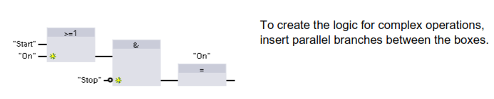
To create the logic for complex operations, you can insert branches to create the logic for parallel circuits. Parallel branches are opened downwards or are connected directly to the power rail. You terminate the branches upwards.
LAD provides “box” instructions for a variety of functions, such as math, timer, counter, and move.
Function Block Diagram (FBD)
Like LAD, FBD is also a graphical programming language. The representation of the logic ibased on the graphical logic symbols used in Boolean algebra.
Mathematical functions and other complex functions can be represented directly in conjunction with the logic boxes.
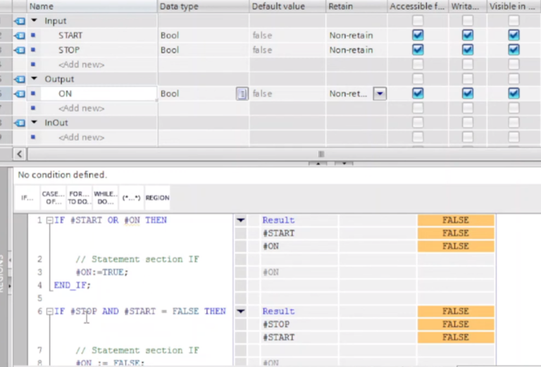
SCL
Structured Control Language (SCL) is a high-level, PASCAL-based programming language for the SIMATIC S7 CPUs. SCL supports the block structure. Your project can include program blocks in any of the three programming languages: SCL, LAD, and FBD.
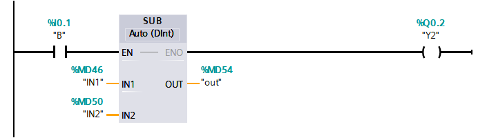
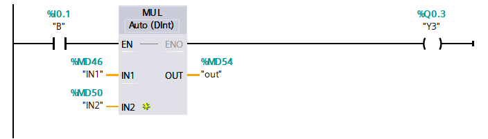
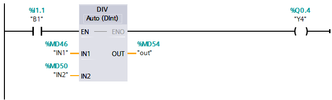
SCL instructions use standard programming operators, such as for assignment (:=), mathematical functions (+ for addition, – for subtraction, * for multiplication, and / for division)SCL also uses standard PASCAL program control operations, such as IF-THEN-ELSE, CASE, REPEAT-UNTIL, GOTO and RETURN. You can use any PASCAL reference for syntactical elements of the SCL programming language. Many of the other instructions for SCL, such as timers and counters, match the LAD and FBD instructions. For more information about specific instructions, refer to the specific instructions in the chapters for Basic instructions .
You can designate any type of block (OB, FB, or FC) to use the SCL programming language at the time you create the block. provides an SCL program editor that includes the following elements:
● Interface section for defining the parameters of the code block
● Code section for the program code ● Instruction tree that contains the SCL instructions supported by the CPU
You enter the SCL code for your instruction directly in the code section. The editor includes buttons for common code constructs and comments. For more complex instructions, simply drag the SCL instructions from the instruction tree and drop them into your program. You can also use any text editor to create an SCL program.
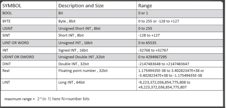
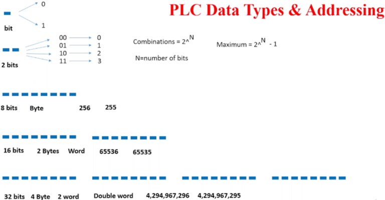
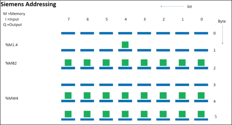
Section-4: PLC Data types and PLC Addressing.
PLC Data types & Addressing
Section-5: How to assign IP address to Siemens PLC S7-1200 CPU ?
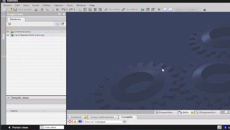
Step-1
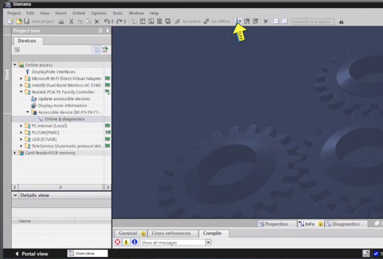
Open “TIA Portal”
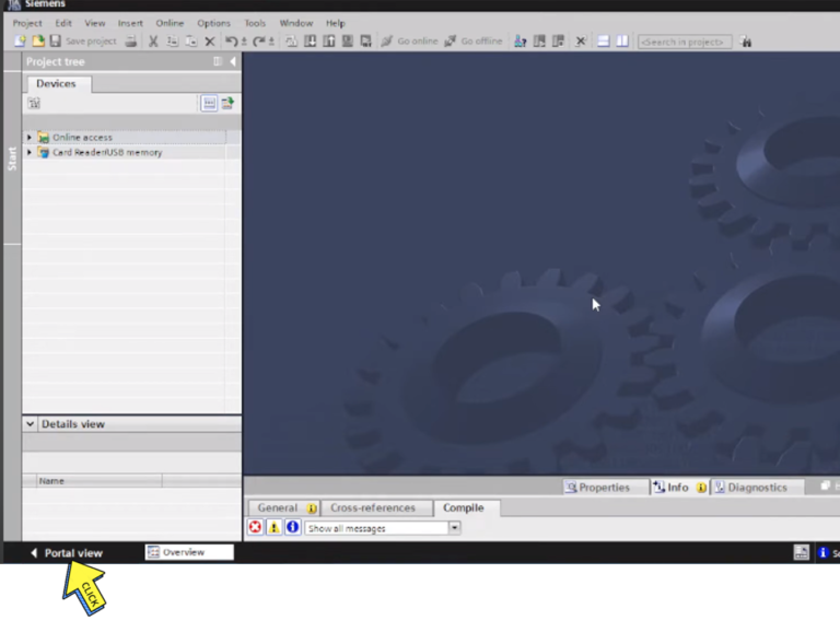
Step-2
Click on “Portal View”.
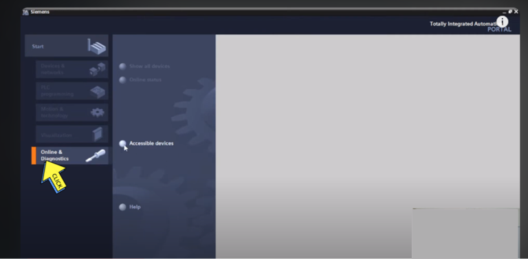
Step-3
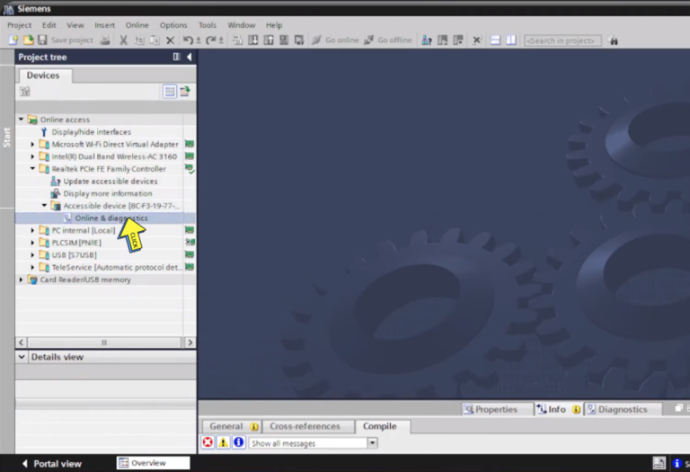
Select on “Online & Diagnostics “
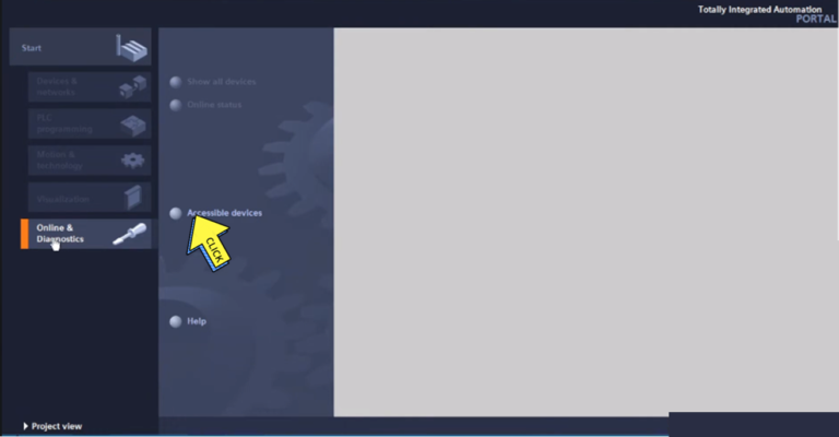
Step-4
Click on “Accessible devices”.
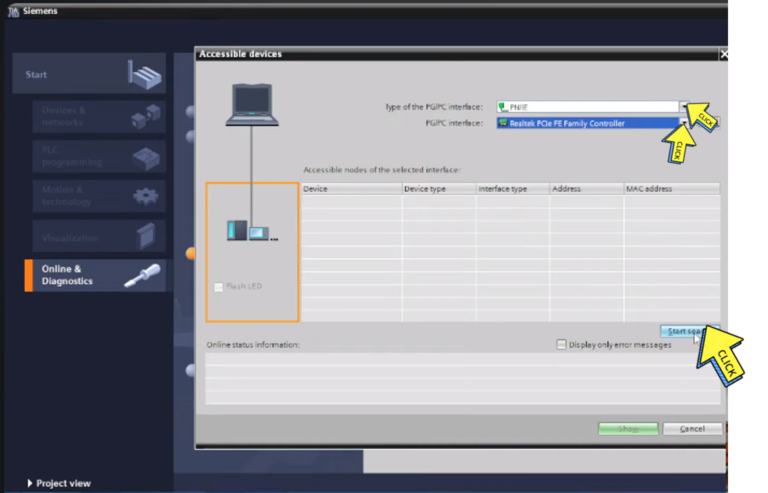
Step-5
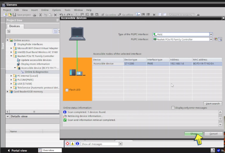
Select on “Type of the PG/PC interface”
“PG/PC interface”.
Click on “Start search.
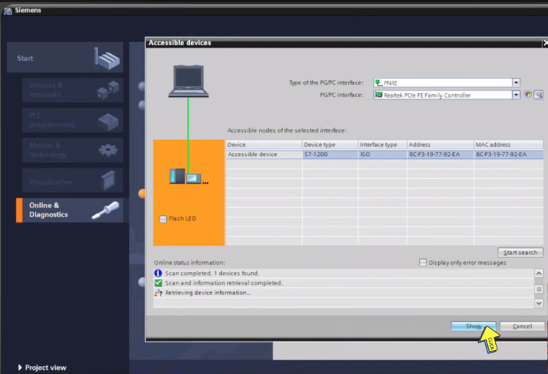
Step-6
Click on ” Show button”
Step-7
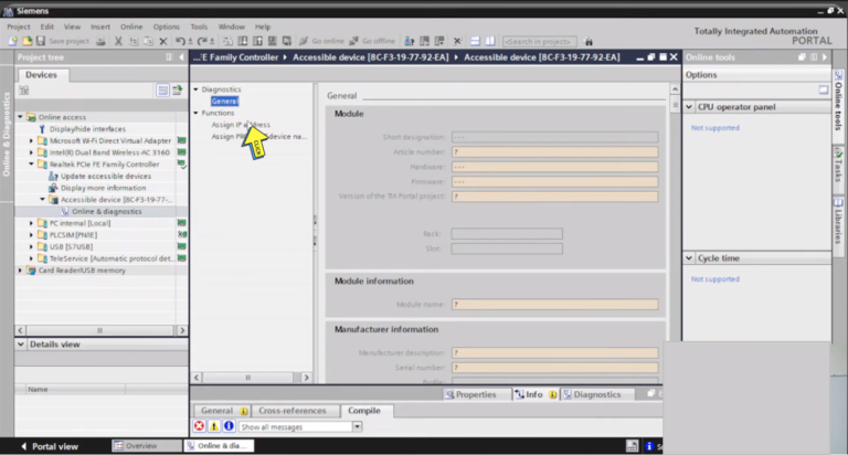
Select on ” Online & diagnostics”.
Step-8
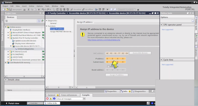
Select on ” Assign IP address “.
Step-9
Set your “IP address”
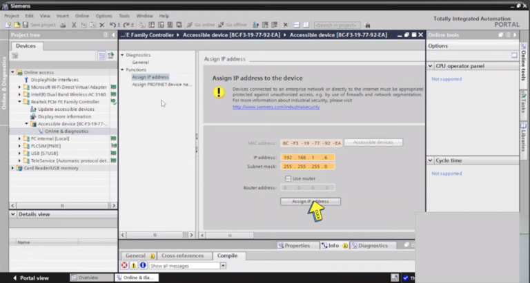
Step-10
Click on “Assign IP Address”.
Step-11
Click on “Search Button”.
Step-12
IP address is set
Section-6 : What is the NO and NC contact and output coil in a Ladder Logic Diagram .
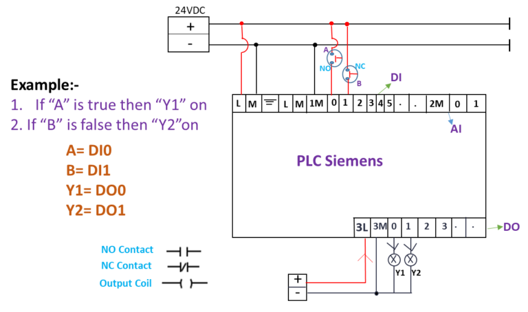
If “A” is true then “Y1” on.
If “B” is false then “Y2” on.
NO Contact
● The Normally Open contact is closed (ON) when the assigned bit value is equal to 1.
NC Contact
● The Normally Closed contact is closed (ON) when the assigned bit value is equal to 0.
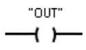
Output Coil
Outputs from a PLC are referred to as coils on a ladder diagram. A coil may represent a motor, light, pump, counter, timer, relay, etc.
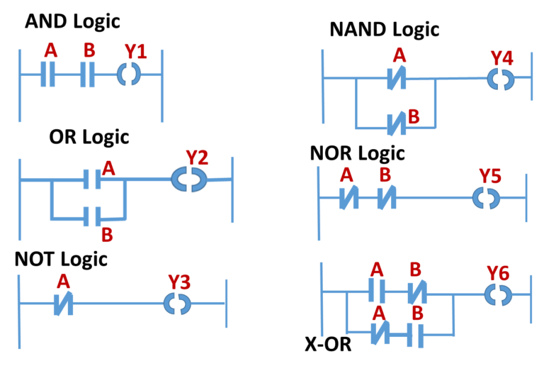
Section-7 : PLC Logic Gates- AND , OR , NOT , NAND , NOR , X-OR , Gate function with ladder Logic diagrams.
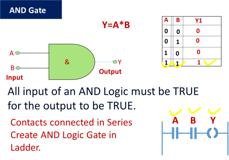
AND Gate.
AND gate:-
Connecting Normally open / XIC contacts in series AND gate can be implemented.
When both input are set to 1, then and then only output goes high.
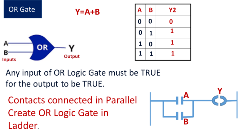
OR Gate.
OR gate:-
Connecting Normally open / XIC contacts in parallel, OR Gate can be implemented.
When either input is set to high, output goes high.
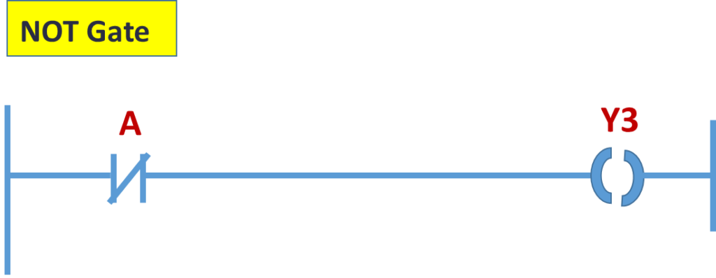
NOT Gate.
NOT gate:-
By using just one Normally Closed / XIO contact, NOT Logic Gate can be implemented.
Inverted state of input is obtained as an output.
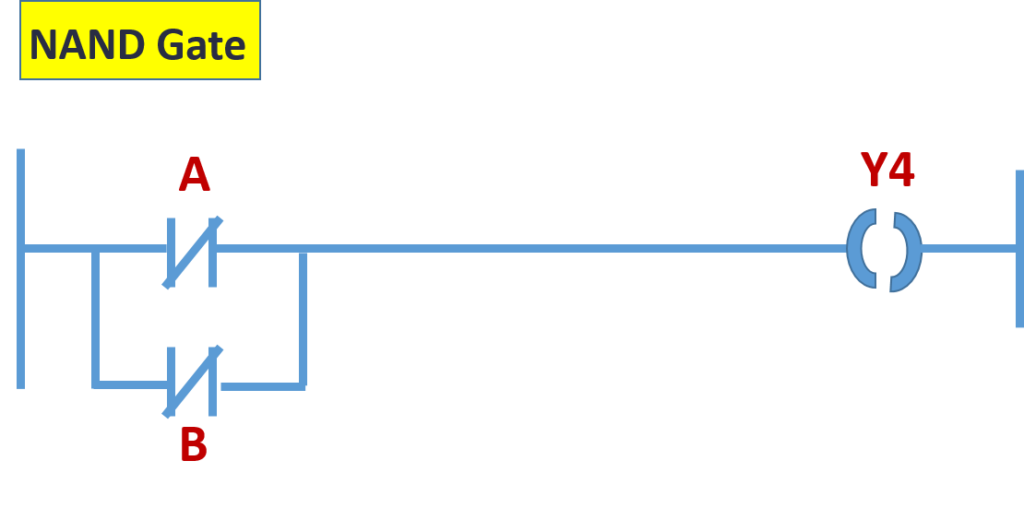
NAND Gate.
NAND gate:-
By connecting Normally Closed contacts in parallel to each other, NAND Gate can be implemented. or by simply inverting output of AND gate, NAND Gate can be implemented.
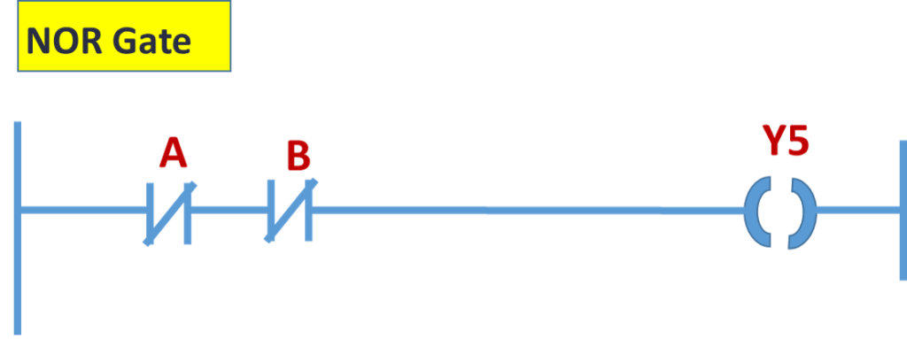
NOR Gate.
NOR gate:-
By connecting Normally Closed / XIO contacts in series, NOR Logic Gate can be implemented.
If both input are reset to 0, output goes High otherwise remains in Low state. or by inverting output of a OR Gate, that is by using output of OR Gate as an input of NOT Gate, NOR Gate can be implemented.
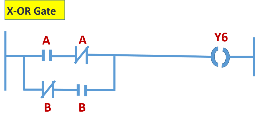
X-OR Gate.
X-OR gate:-
By connecting XIC and XIO in series with parallel to XIO and and XIC in series as shown in diagram above, X- OR Gate can be implemented.
When both input are identical, output is 0. Output id high when A=B
Note here that XIC of first series contacts and XIO of second series contacts must be given same address and similarly for the other two.
Section-8 : SET output Coil and RESET output Coil Instructions.
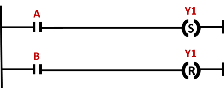
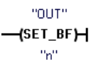
SET output Coil
● Coil are graphic components of Ladder Diagram (LD) programs that represent the assignment of an output or of an internal variable. In LD program, a coil represents an action. Set coil support a Boolean output of a connection line Boolean state.
The associated variable is set to TRUE when the Boolean state of the left connection becomes TRUE. The output variable keeps this value until an inverse order is made by a Reset coil.
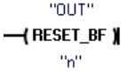
RESET output Coil
Coil are graphic components of Ladder Diagram (LD) programs that represent the assignment of an output or of an internal variable.
Reset coils support a Boolean output of a connection line Boolean state.
The associated variable is reset to FALSE when the Boolean state of the left connection becomes TRUE. The output variable keeps this value until an inverse order is made by a Set coil.
Tutorial Assignment:
Example:-
IF “A” push button is pressed then “Y1” true & True until “B” Push button is pressed.
Section-9 : SET & RESET BIT FIELD logic instructions.
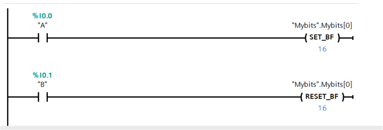
Set bit field
Set bit field:-
When SET_BF is activated, a data value of 1 is assigned to “n” bits starting at address tag OUT. When SET_BF is not activated, OUT is not changed.
Reset bit field
Reset bit field:-
RESET_BF writes a data value of 0 to “n” bits starting at address tog OUT. When RESET_BF is not activated, OUT is not changed.
Section-10 : What are SR and RS Flip - Flops in PLC?
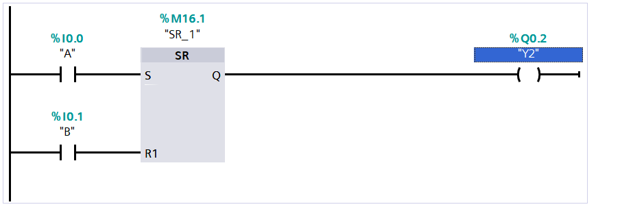
SR Flip- Flop
Set/reset flip-flop: SR is a reset dominant latch where the reset dominates. If the set (S) and reset (R1) signals are both true, the value at address SR_1 will be 0.
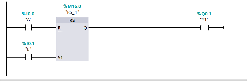
RS Flip- Flop
Reset/set flip-flop: RS is a set dominant latch where the set dominates. If the set (S1) and reset (R) signals are both true, the value at address RS_1 will be 1.
Section-11 : Positive and Negative Edge Signals Detection. Trigger Signal Detection.
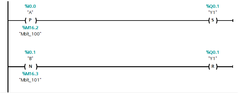
Positive / Negative Edge
–(P)–:
Set operand on positive signal edge.
–(N)–:
Set operand on Negative signal edge.
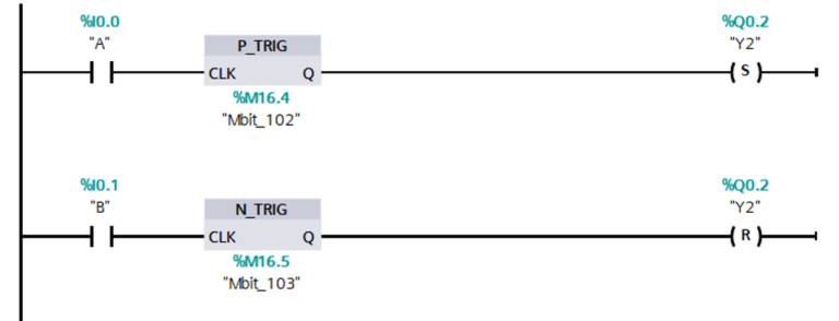
Positive / Negative Edge Trigger
P_TRIG:
The Q output logic state is TRUE when a positive transition (OFF-to-ON) is detected on the CLK input state in (LAD).
N_TRIG:
The Q output logic state is TRUE when a negative transition(ON-to-OFF) is detected on the CLK input state in (LAD).
Section-12 : Timer Instructions.
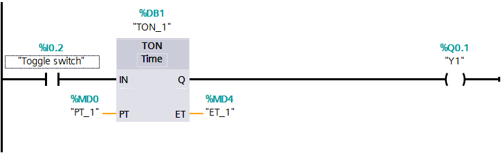
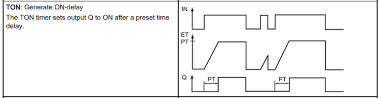
TON - ON Delay Timer
The on delay timer starts when the timer trigger bit is true, and the timer output “Q” is turned on when the preset time elapses.
On- delay timers are typically used in application where it is important to ensure that a circuit is not activated until after a certain amount of time has elapsed.
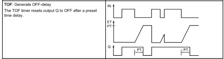
TOF- OFF Delay Timer
OFF Delay Timer, the timer output bit turns OFF when the setup time has passed after the timer input bit had turned OFF.
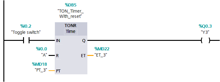
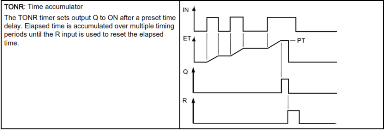
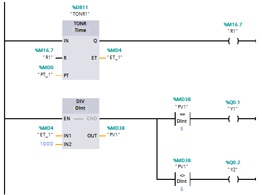
Retentive on delay Timer (TONR)
Retentive On Delay Timer or On Delay Timer with reset (TONR): The main function of the TONR is used to hold or store the set (accumulated) time.
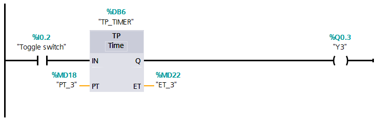
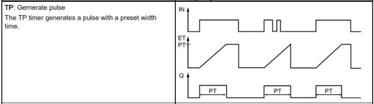
Pulse Generate Timer - TP
The TP timer generates a pulse with a preset width time.
Section-13 : Counter Instructions.
Description:
Use the counter instruction to count internal program events and external process events. Each counter uses a structure stored in a data block to maintain counter data. You assign the the data block when the counter instruction is placed in the editor.
CTU is a count-up counter
CTD is a count-down counter
CTUD is a count- and- counter
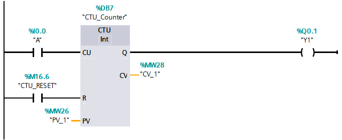
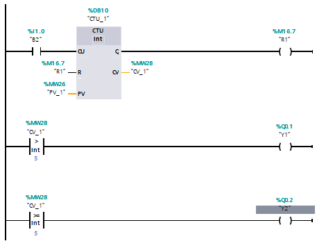
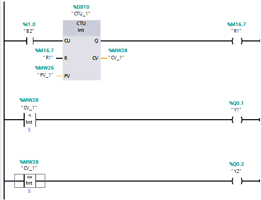
Count Up Counter (CTU)
CTU (count up) Counter:
Counts integers from 0 up to a given value, 1 by 1.
Counts upward. When the CU input bit is TRUE then count upward in increments of one. when the CU input bit is FALSE then hold the counter value at the same value.
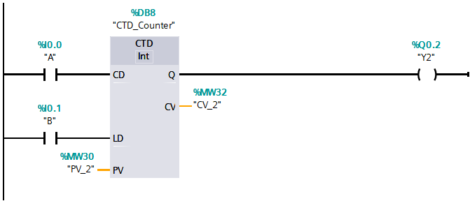
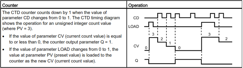
Count Down Counter (CTD)
CTD (count down) Counter:
when the CU input bit is TRUE then count down in decrements of one.
When the CU input bit is TRUE then hold the counter value at the same value.
Counts integers from a given value down to o,1 by 1.
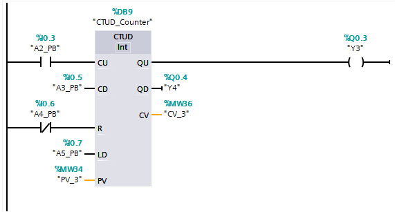
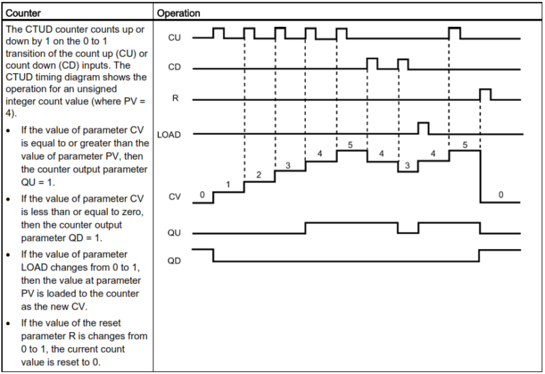
What is Count-UP & Count Down Mixed Counter (CTUD)
CTUD Counter:
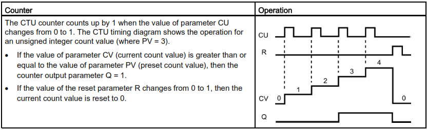
The CTUD counter counts up or down by 1 on the 0 to 1 transition of the count up (CU) or count down (CD) inputs. The CTUD timing diagram shows the operation for an unsigned integer count value
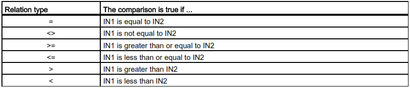
Section-14 Compare Instructions.
Greater than , "Greater than or equal to"
Greater than
Greater than or equal
Less than , "Less than or equal to"
Less than
Less than or equal
Equal, Not Equal
Equal
Not Equal
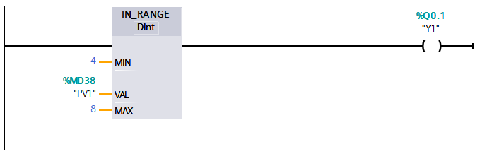
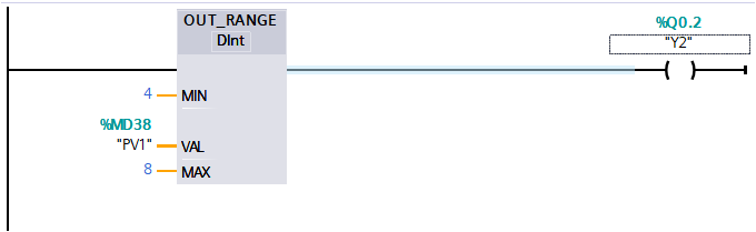
IN_Range (Value within range) and OUT_Range (Value outside range)
instructions
Tests whether an input value is in or out of a specified value range.If the comparison is TRUE, then the box output is TRUE.
IN Range
The IN_RANGE comparison is true if: MIN <= VAL <= MAX
OUT
Range
The OUT_RANGE comparison is true if: VAL < MIN or VAL > MAX
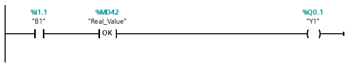
OK (Check validity) and NOT_OK (Check invalidity) instructions
Tests whether an input data reference is a valid real number.
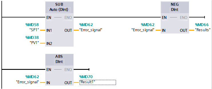
The NEG instruction inverts the arithmetic sigh of the value at parameter IN and stores the result in parameter OUT.
ABS :-
Calculates the absolute value of a signed integer or real number at parameter S7-1200 Programmable controller IN and stores the result in parameter OUT.
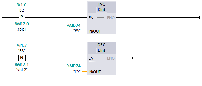
INC (Increment) and DEC (Decrement) using Positive & Negative Edge.
INC:-
Increments a signed or unsigned integer number value:
IN_OUT value +1 = IN_OUT value.
DEC :-
Decrements a signed or unsigned integer number value:
IN_OUT value -1 = IN_OUT valu.
–(P)–: Set operand on positive signal edge.
–(N)–: Set operand on negative signal edge.
Edge detection VS Edge Trigger:
The main difference between “edge detection” and “level triggering” is that in edge detection, the output of the sequential circuit changes during the high voltage period or low voltage period .
while, in level triggering, the output of the sequential circuit changes during transits from the high voltage to low voltage or low voltage to high voltage.
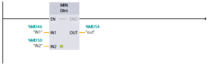
MIN (Get minimum)
MIN:-
The MIN instruction compares the value of two parameters IN1 and IN2 and assigns the minimum (lesser) value to parameter OUT.
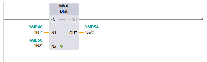
MIX (Get maximum)
MAX:-
The MAX instruction compares the value of two parameters IN1 and IN2 and assigns the maximum (greater) value to parameter OUT.
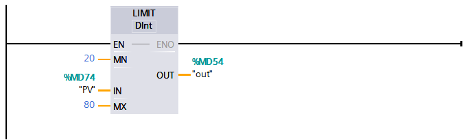
Limit (Set Limit value)
LIMIT:-
The Limit instruction tests if the value of parameter IN is inside the value range specified by parameters MIN and MAX and if not, clamps the value at MIN or MAX.
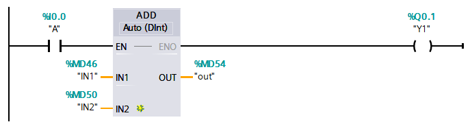
Section- 16 Move operations
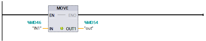
Use the Move instructions to copy data elements to a new memory address and convert from one data type to another. The source data is not changed by the move process.
The MOVE instruction copies a single data element from the source address specified by the IN parameter to the destination addresses specified by the OUT parameter.
MOVE (Move value)
MOVE :
● Copies a data element stored at a specified address to a new address or multiple addresses.
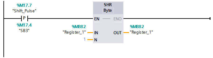
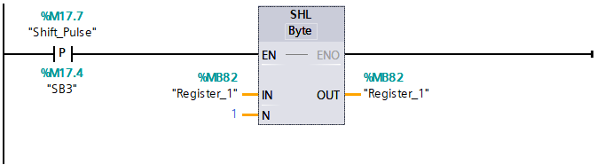
Section-17 SHR (Shift right) and SHL (Shift left) instructions.
Use the shift instructions (SHL and SHR) to shift the bit pattern of parameter IN. The result is assigned to parameter OUT. Parameter N specifies the number of bit position shifted:
SHR (Shift right)
SHR: Shift bit pattern right
SHL (Shift left)
SHL: Shift bit pattern left
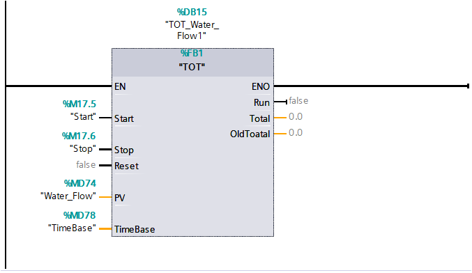
Section-18 Totalizer
Flow _ Totalizer
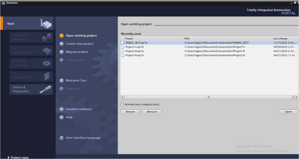
Section-19 How to Upload or take Backup of Siemens?
Upload program.
Step 1:-
Open “TIA Portal”
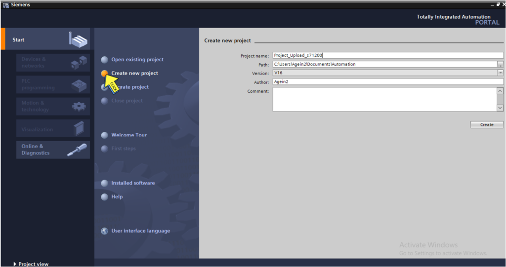
Step 2:-
Create new project
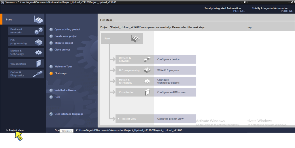
Step 3:-
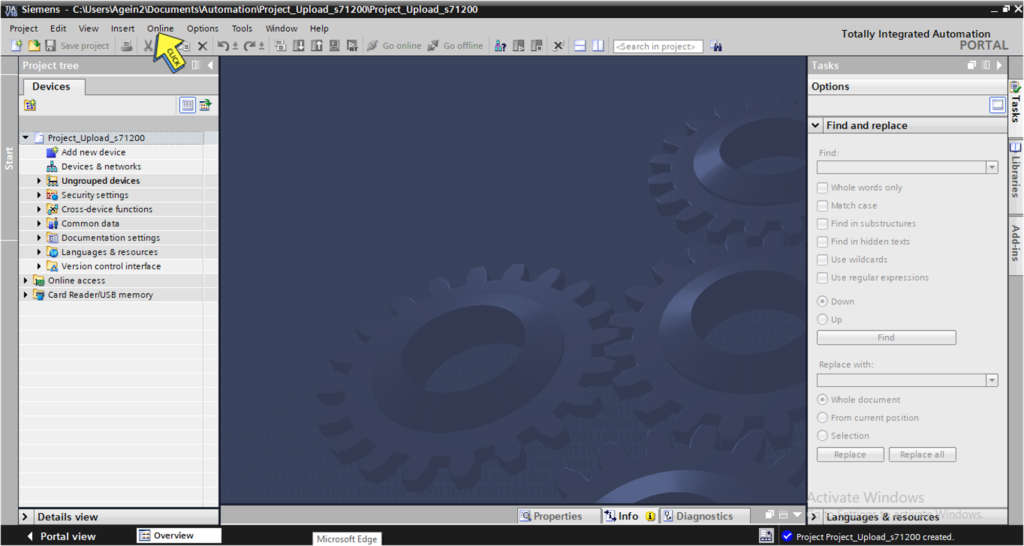
Click on “Project view
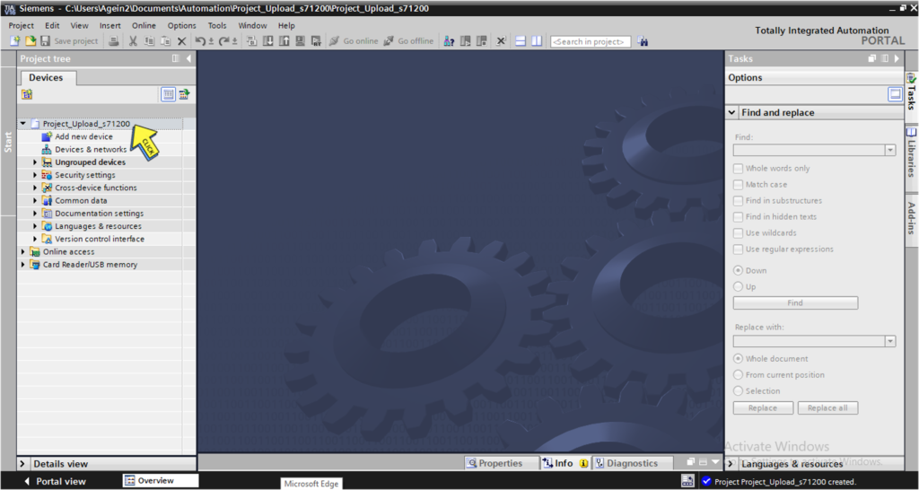
Step 4:-
Select on your “Project”
Step 5:-
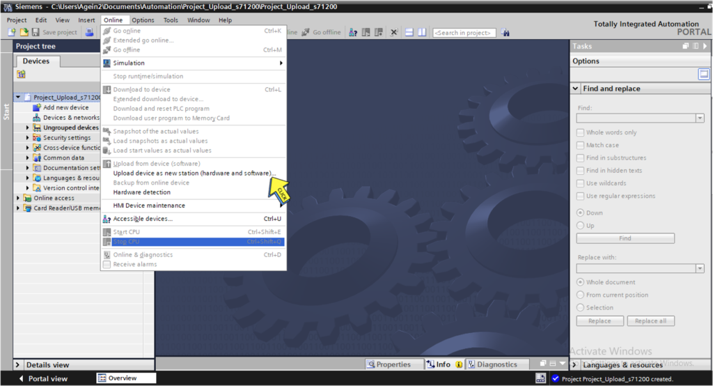
Click on “Online” button
Step 6 :-
Click on “Upload device as new station”
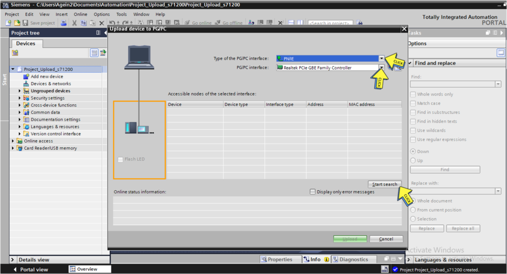
Step 7 :-
Select “Type of the PG/PC interface”
Select “PG/PC interface”
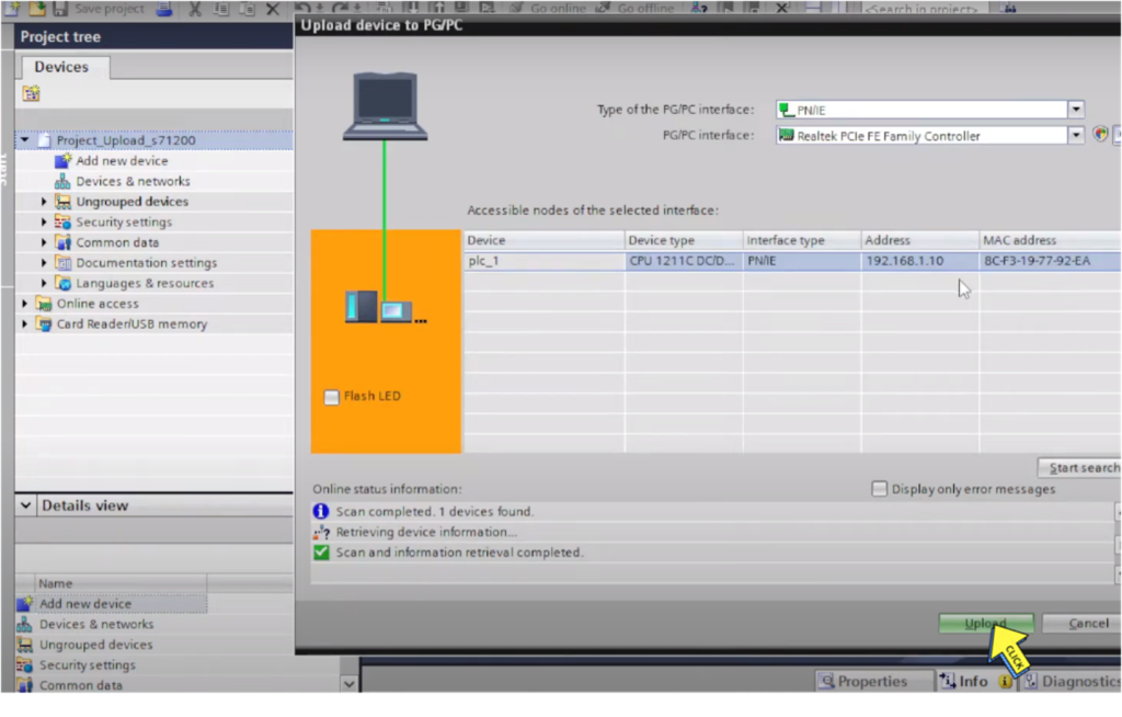
Click On “Start search” button
Click on “Upload” button
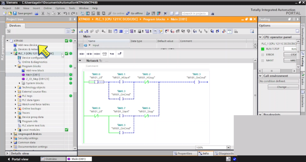
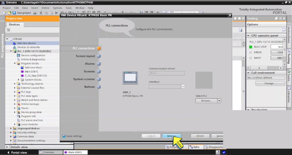
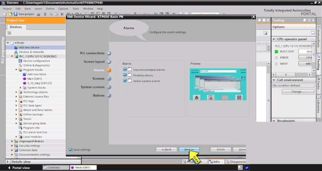
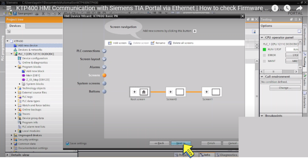
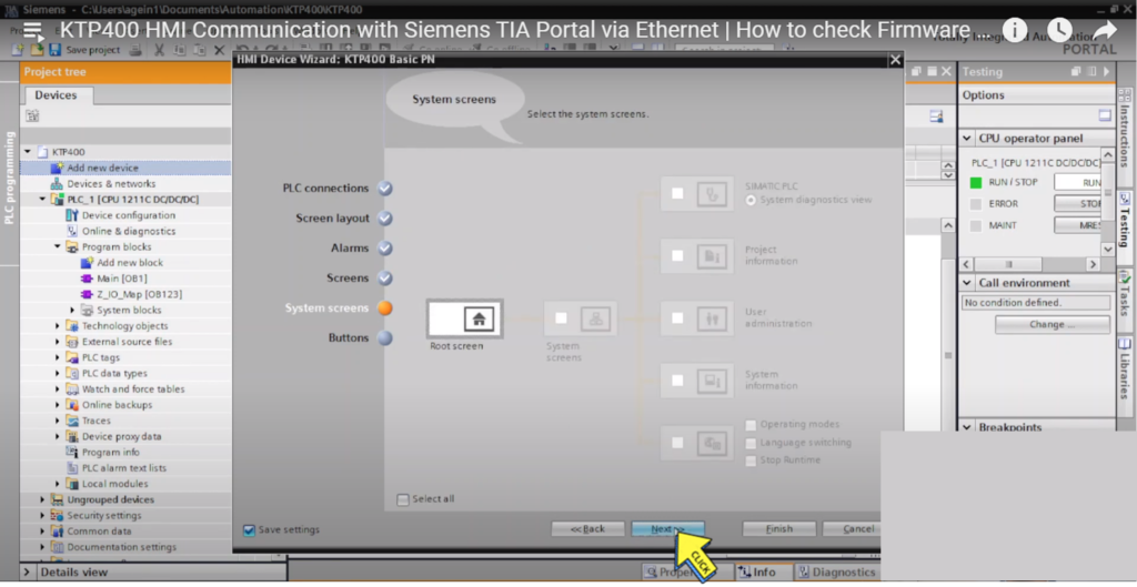
Section-20: KTP400 HMI Communication with Siemens TIA Portal via Ethernet
KTP400 HMI Communication.
Step 1:
Select “Add new device”
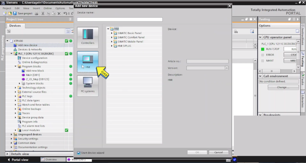
Step 2:
Click on “HMI “
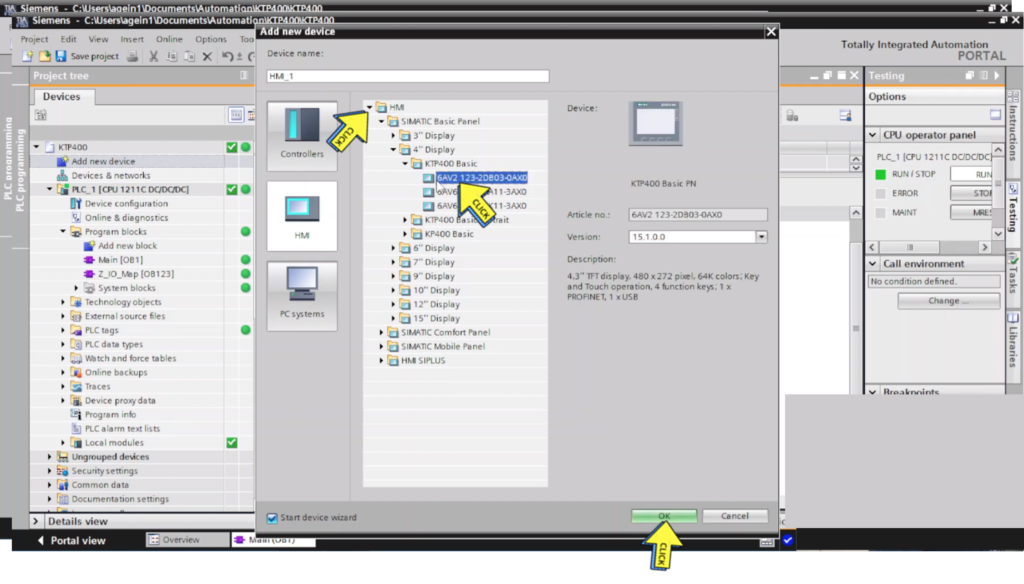
Step 3:
Select on “HMI Series “
Click on “OK button”
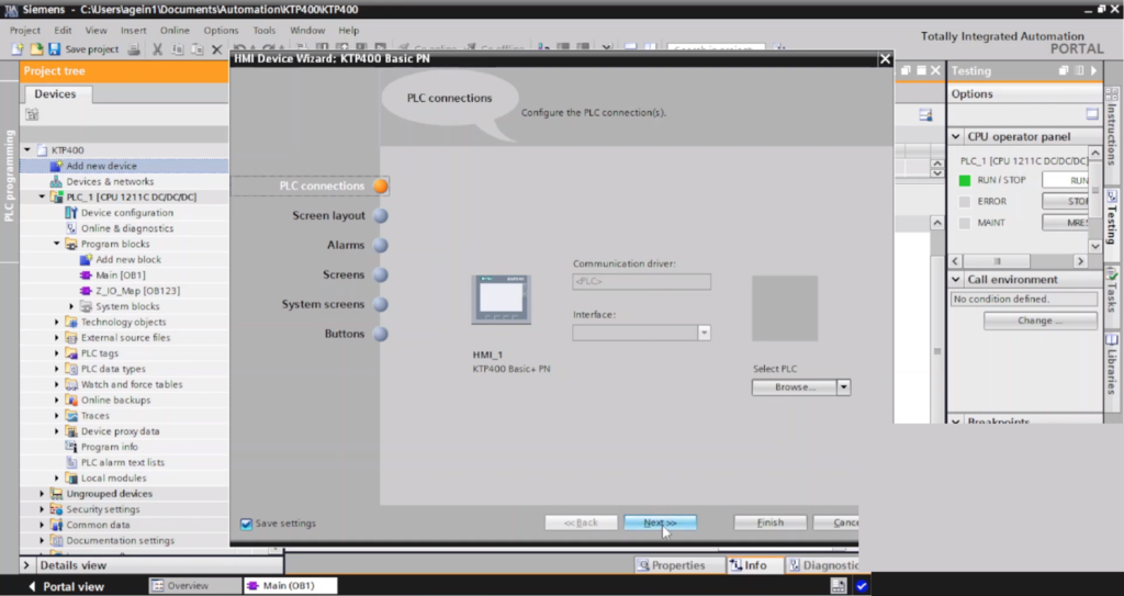
Step 4:
Create on “HMI Project”
Step 5:
Next >>
Step 6:
Next >>
Step 7:
Next >>
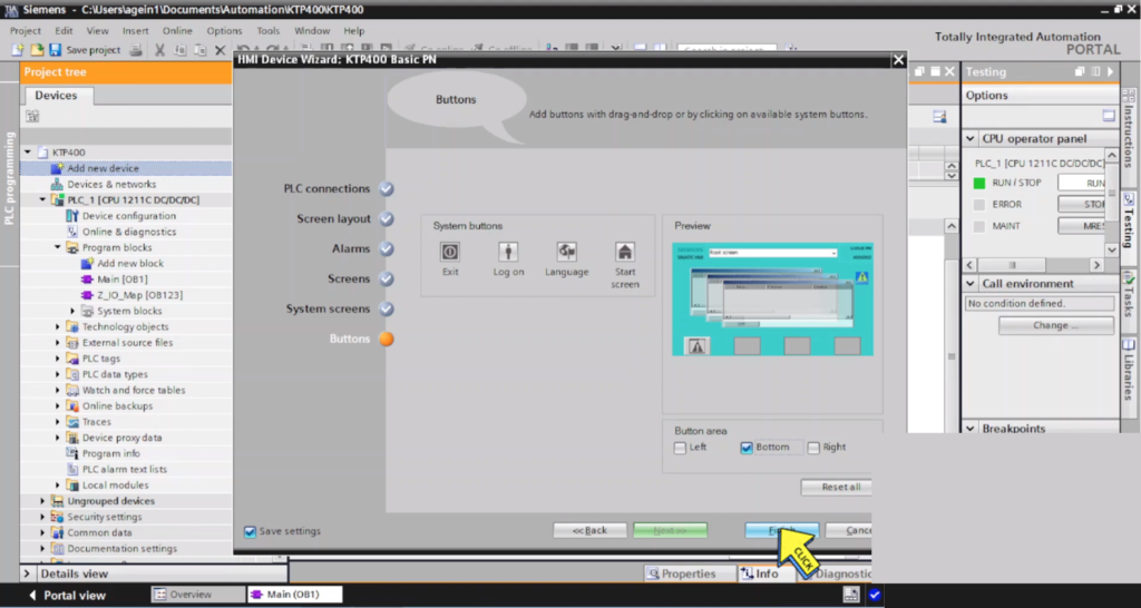
Step 8:
Next >>
Step 9:
Click on “Finish button”
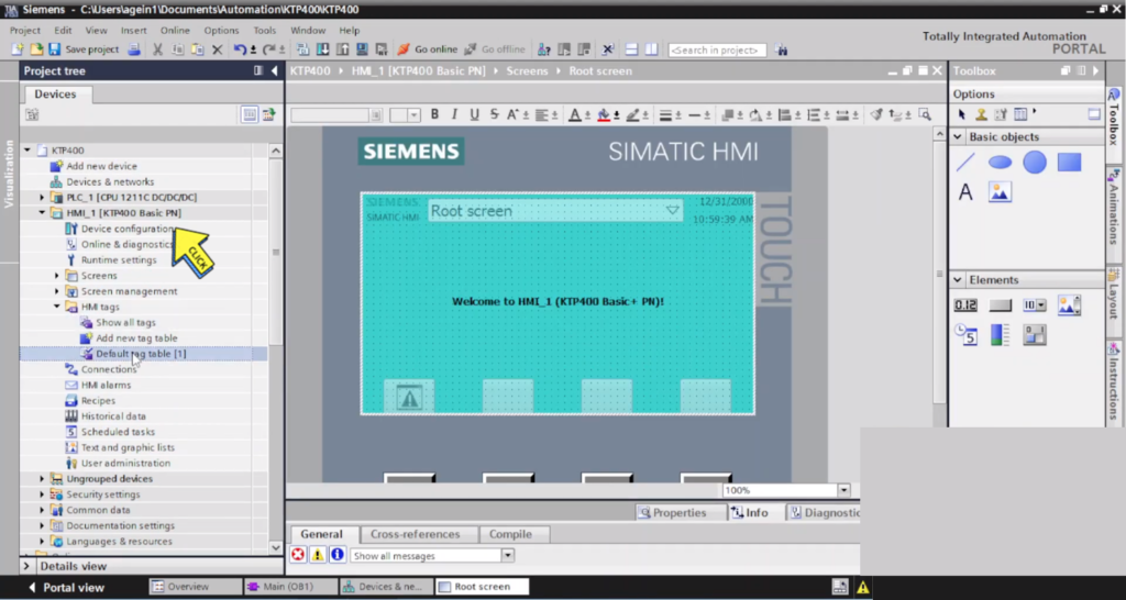
Step 10:
Click on “Device configuration”
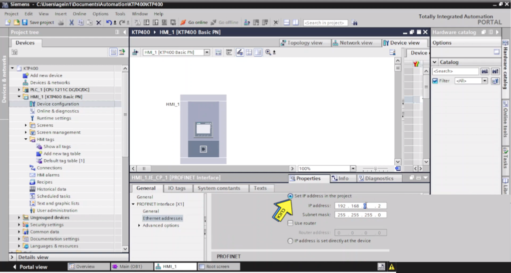
Step 11:
Set “IP address” in the project.
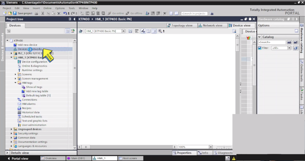
Step 12:
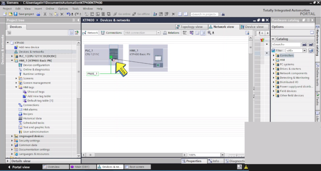
Click on “Devices & networks”
Step 13:
Create Communication “HMI to PLC”
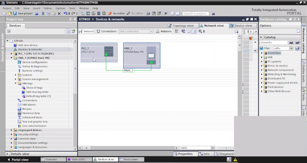
Step 13:
Communication Completed.
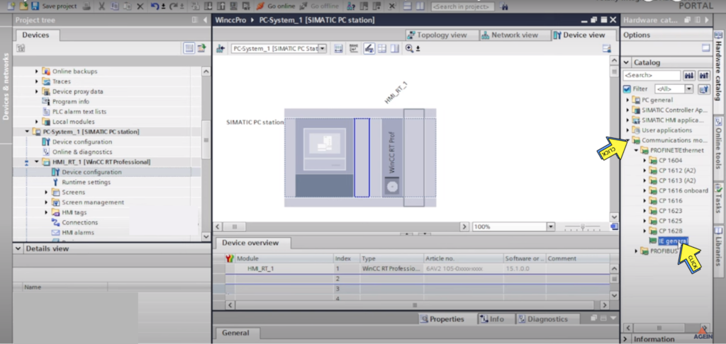
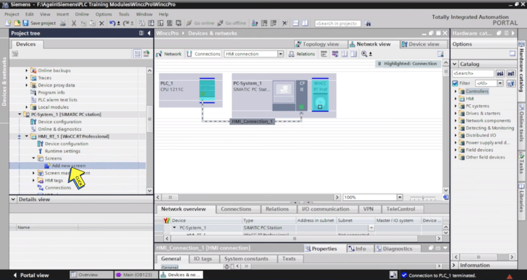
Section-21: WinCC RT Professional communication with S7-1200 PLC Momentary Button in WINCC Professional
WinCC RT Professional communication with S7-1200 PLC
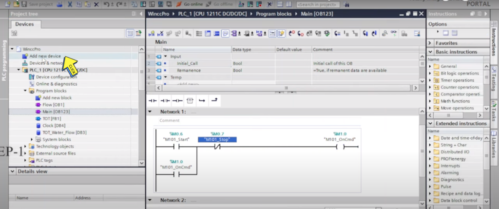
Step 1:
Click on “Add New Device”
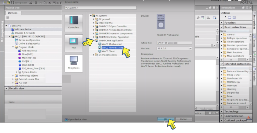
Step 2:
Click on “SIMATIC HMI application”
Select “Wincc RT Professional”
Click On “Ok Button”
Step 3:
Click On “Communications”
Select “IE general”
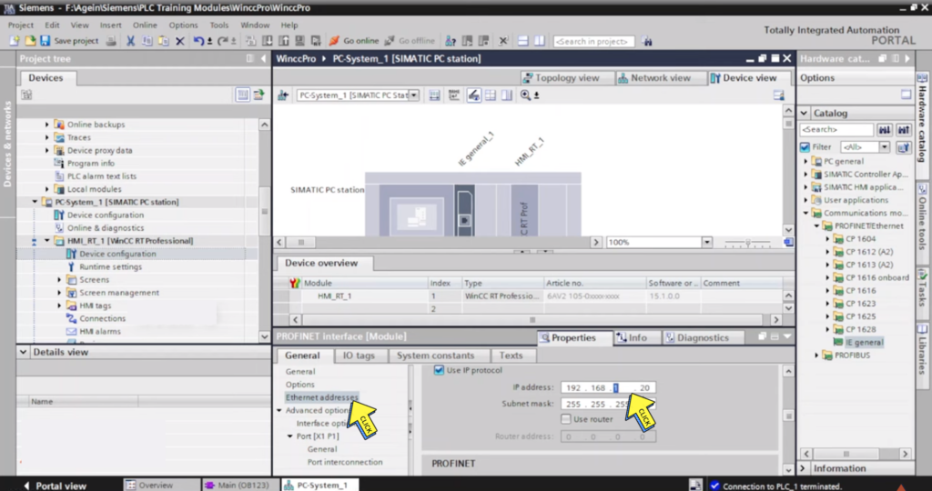
Step 4:
Select “Ethernet addresses”
Set “IP Address”
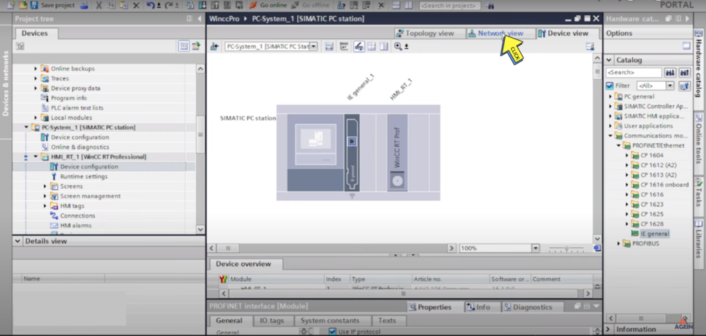
Step 5:
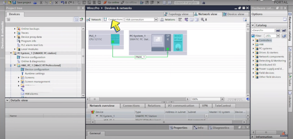
Click On “Network View”
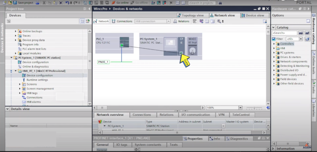
Step 6:
Connect the Ethernet Cable “PLC to PC System with Ethernet Cable ”
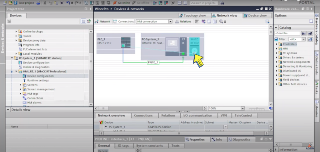
Step 7:
Click on “Connections”
Step 8:
Contacted the Cable “PLC to WinCC RT Prof ”
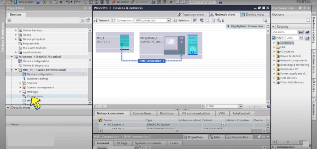
Step 9:
Click on “Connections”
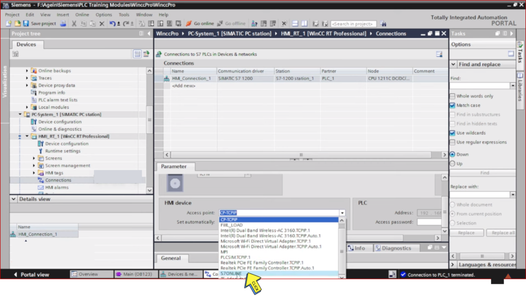
Step 10:-
Select On HMI device “S7ONLINE”
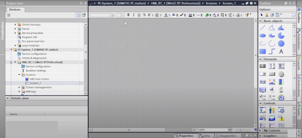
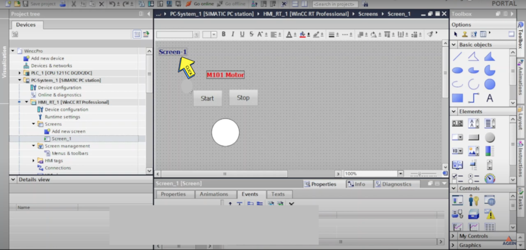
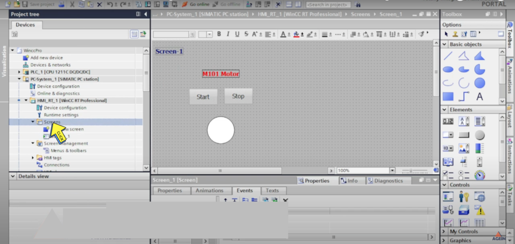
Add New Screen Momentary Button in WINCC Professional.
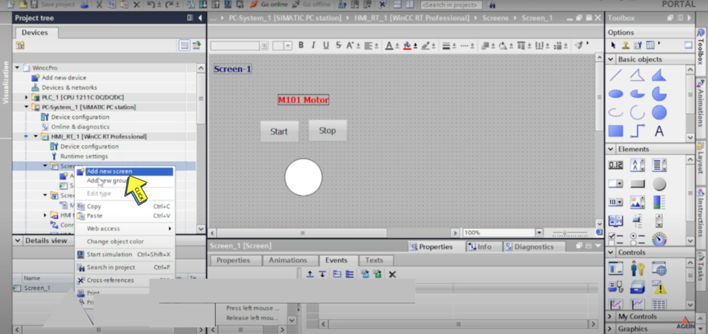
Step 1:-
Click on “Add new screen”
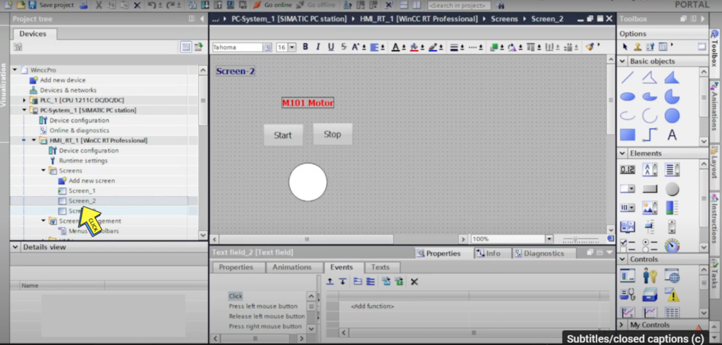
Step 2:-
“Created New Screen”
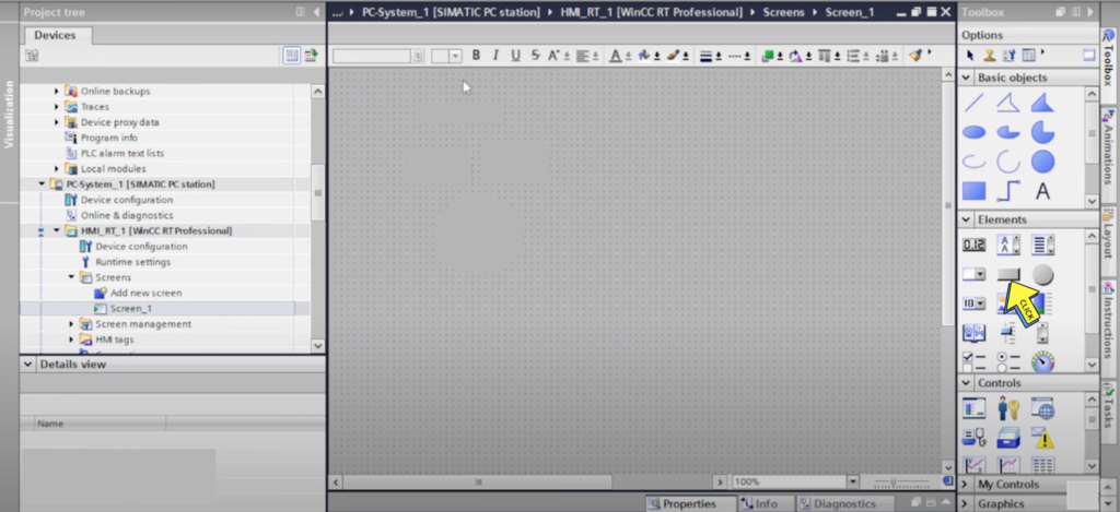
Step 3:-
Select on “Momentary Button”
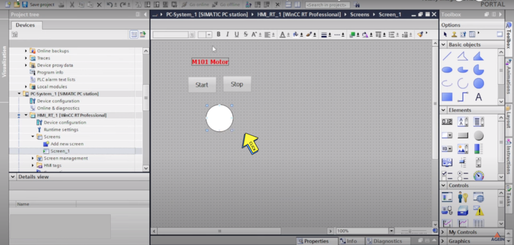
Step 4:-
Created “Scada button and Object”
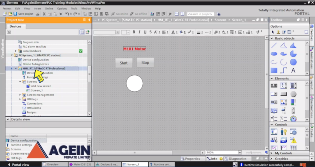
How to Generate runtime File & AutoStart in WinCC Professional TIA Portal?
Step 1:-
Click on “HMI_RT_1[WinCC RT Professional”
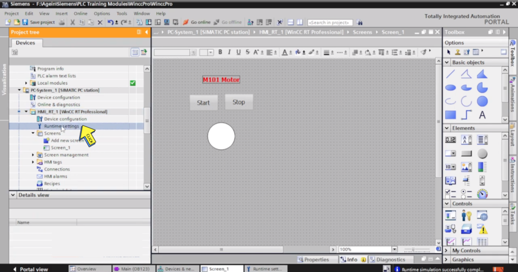
Step 2:-
Click on “Runtime Setting”
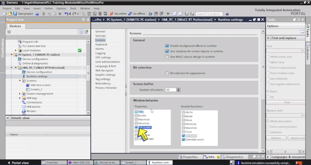
Step 3 :-
Click on “Screens”
Step 4:-
Tick on “Full Screen”
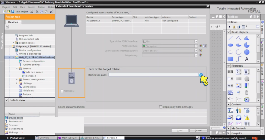
Step 5 :-
Program “Save the Folder”
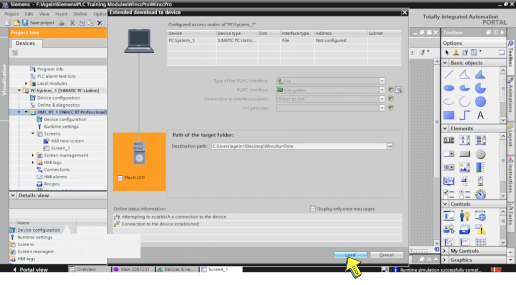
Step 6 :-
Click on “Destination Path”
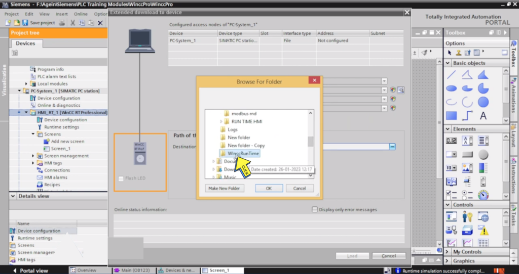
Step 7 :-
Click on “Browse For Folder“
Select the “Program File”
Step 8 :-
Click on “Load Button”
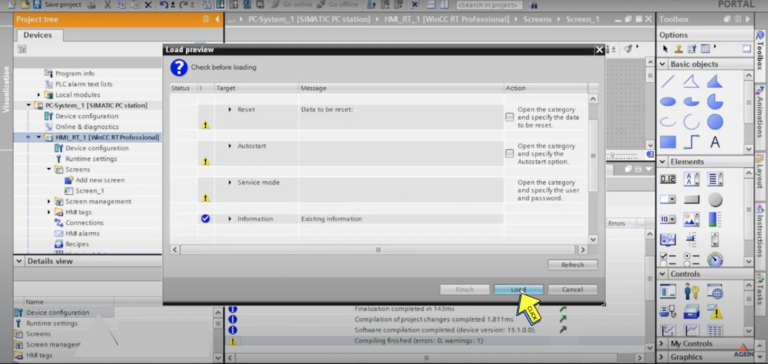
Step 9:-
Click on “Load button”
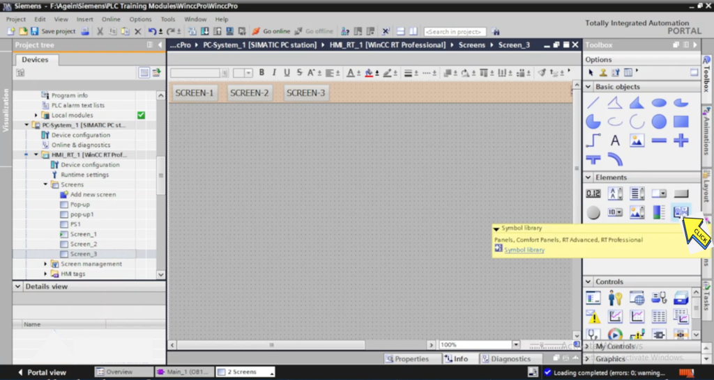
Screen Navigation Button Configuration in Wincc RT Professional | How to change screen in WinCC Pro?
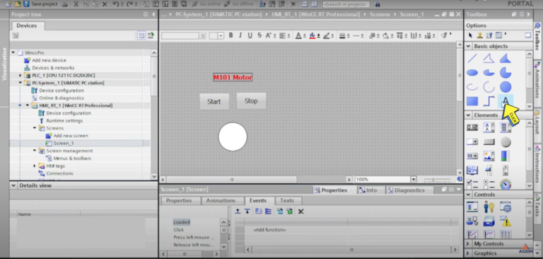
Step 1:-
Click on “Text”
Step 2:-
Create “Screen Name”
Step 3:-
Click on “Screen”
Step 4:-
Click on “Add new Screen”
Step 5:-
Created ” SCADA Screen”
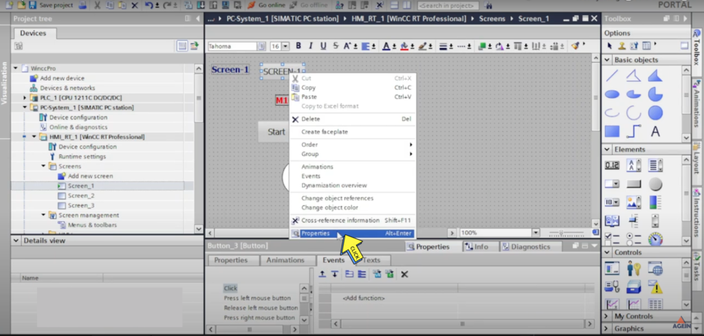
Step 6:-
Click on “Properties”
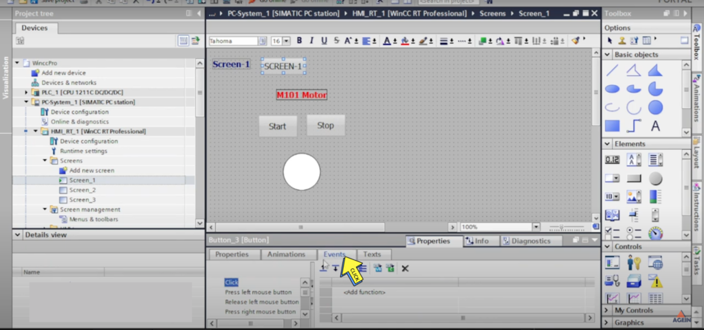
Step 7:-
Click on “Events”
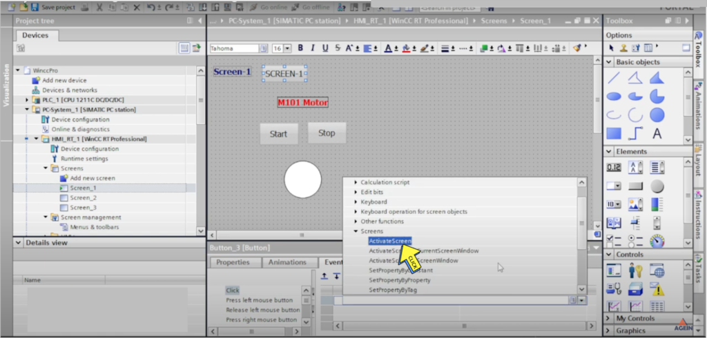
Step 8:-
Click on “Activate Screen”
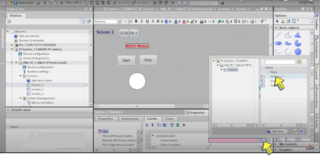
Step 9:-
Click on ” Screen name “
Select on “Screen”
Step 10:-
“Screen Navigation Buttons”
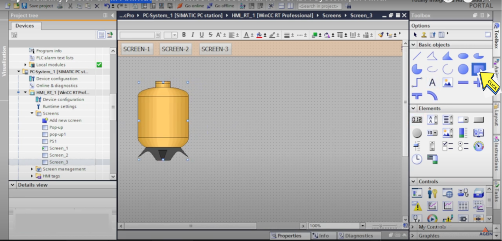
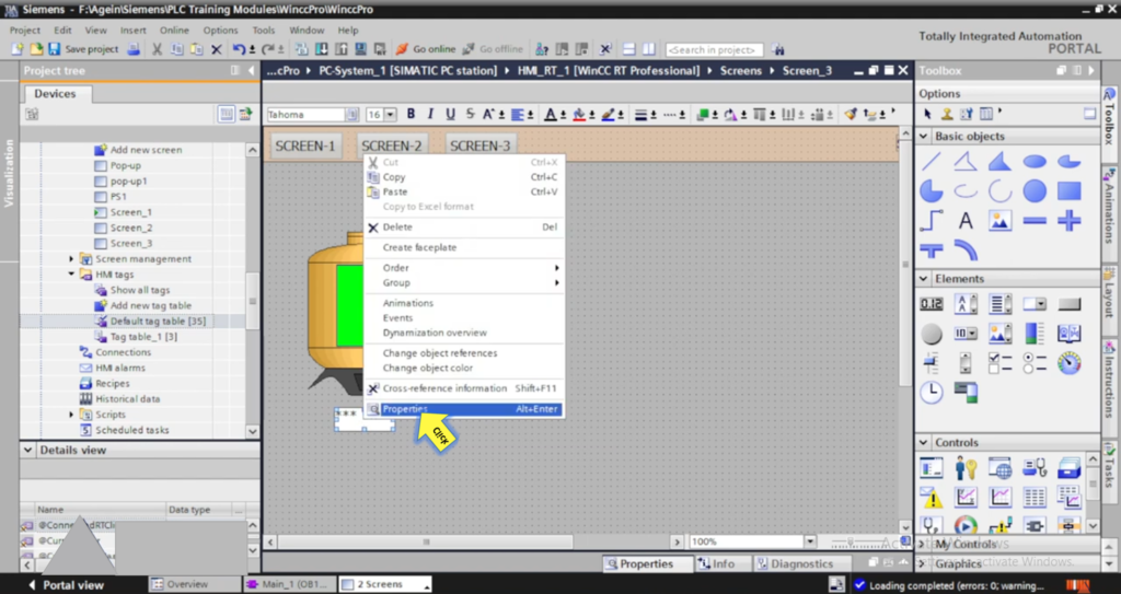
Section-22 : Motor Popup in TIA Portal RT Professional | Screen window configuration & Tag Prefix
how to make pop-up screen using screen window?
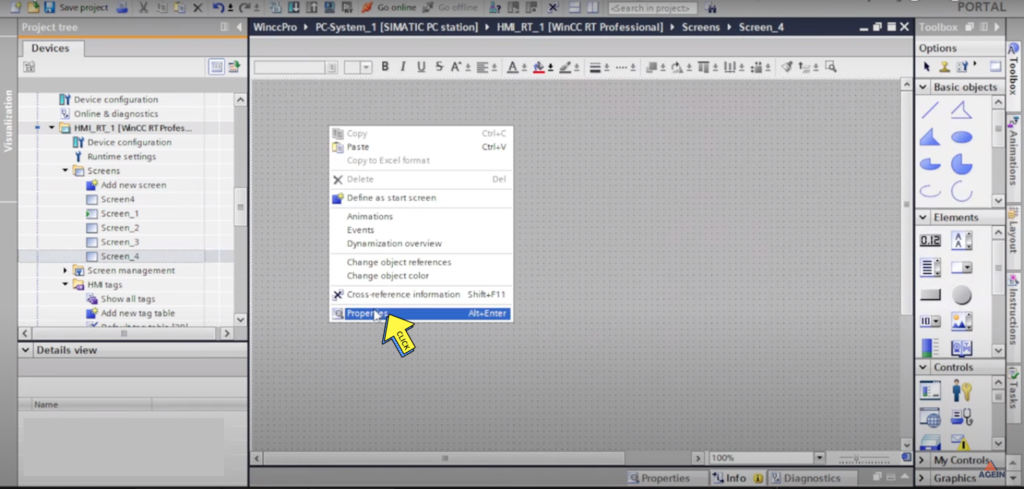
Step 1:-
Click on “Add New Screen”
Step 2:-
Click on” Property”
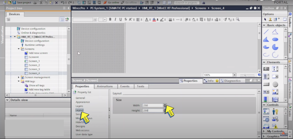
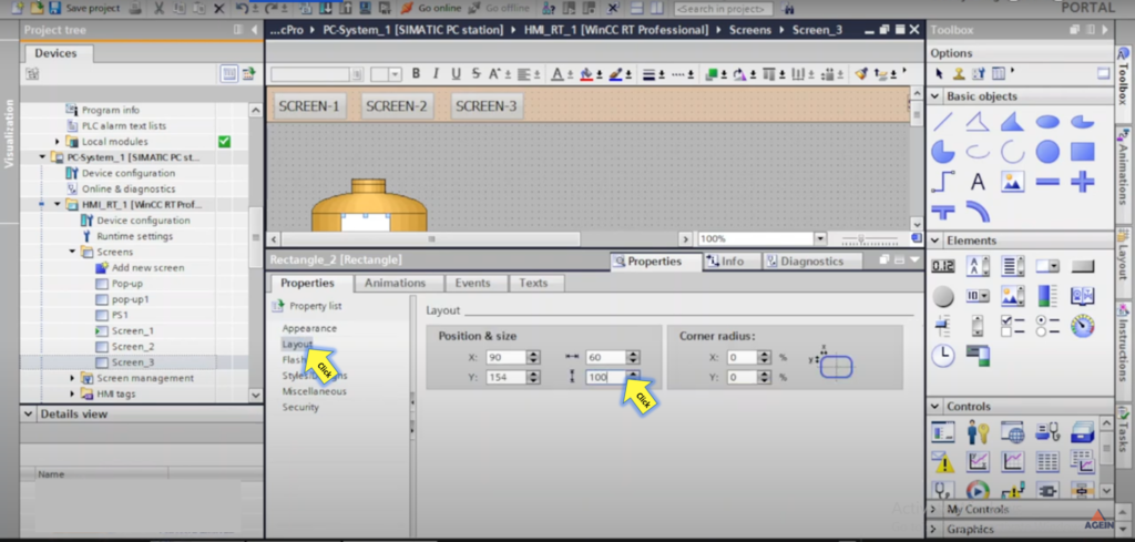
Step 3 :-
Click on “Layout”
Click on Size “Width and Haight
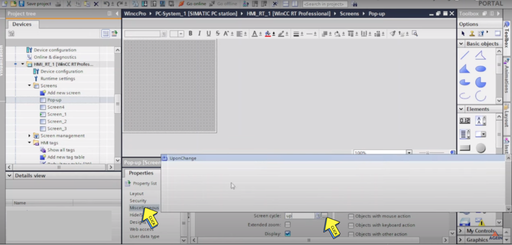
Step 4 :-
Click on “Miscellaneous And Screen Cycle “
Select Screen
Step 5 :-
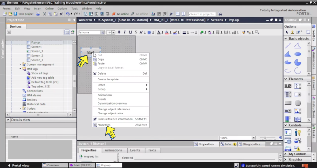
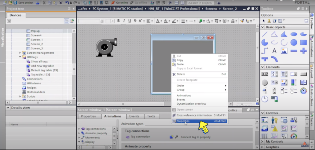
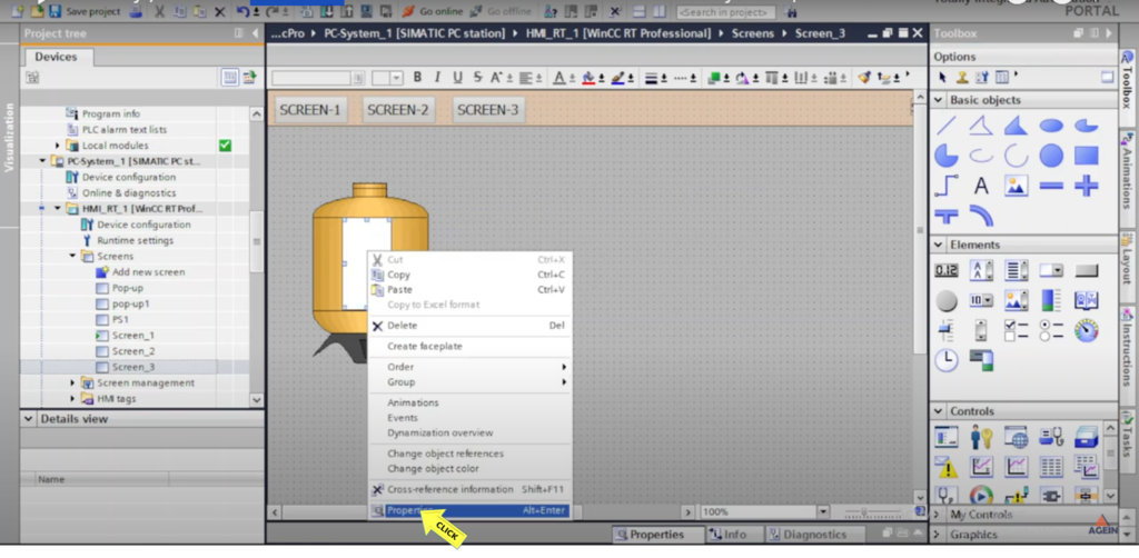
Right Click on “Button”
And Click on “Property”
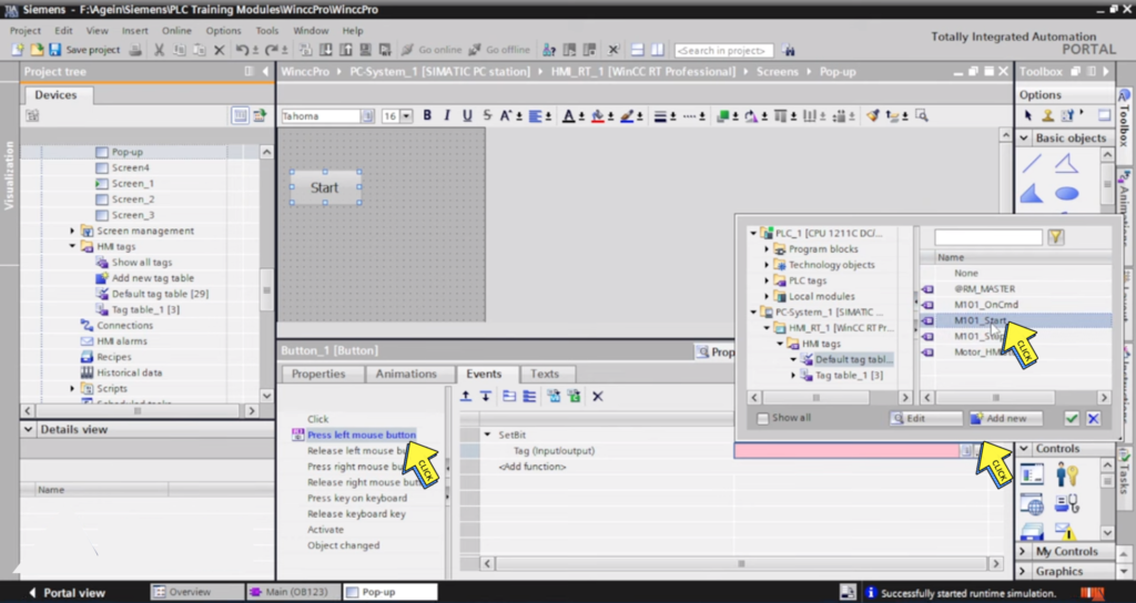
Step 6 :-
Select on “Press Left mouse button” AND
Click on “Tag”
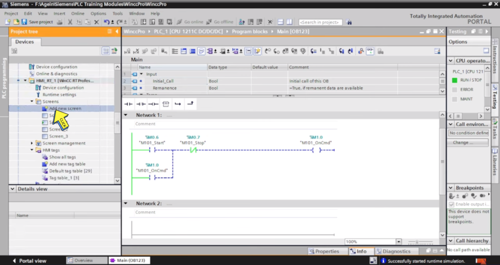
Click on ” M101_Start”
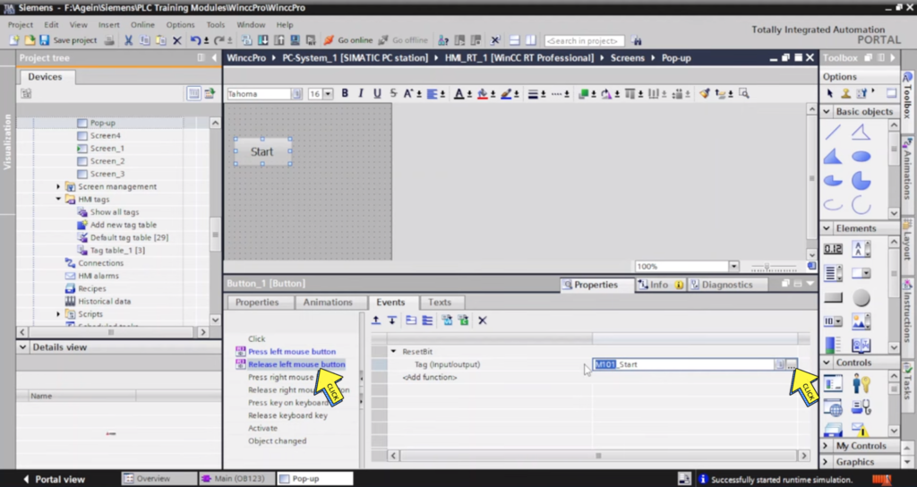
Step 7 :-
Select on “Release left mouse button” and
Click on “Reset Bit ”
Select the “M101_Stop”
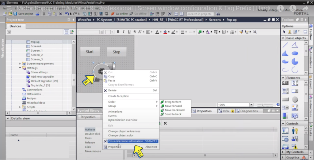
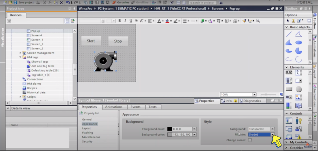
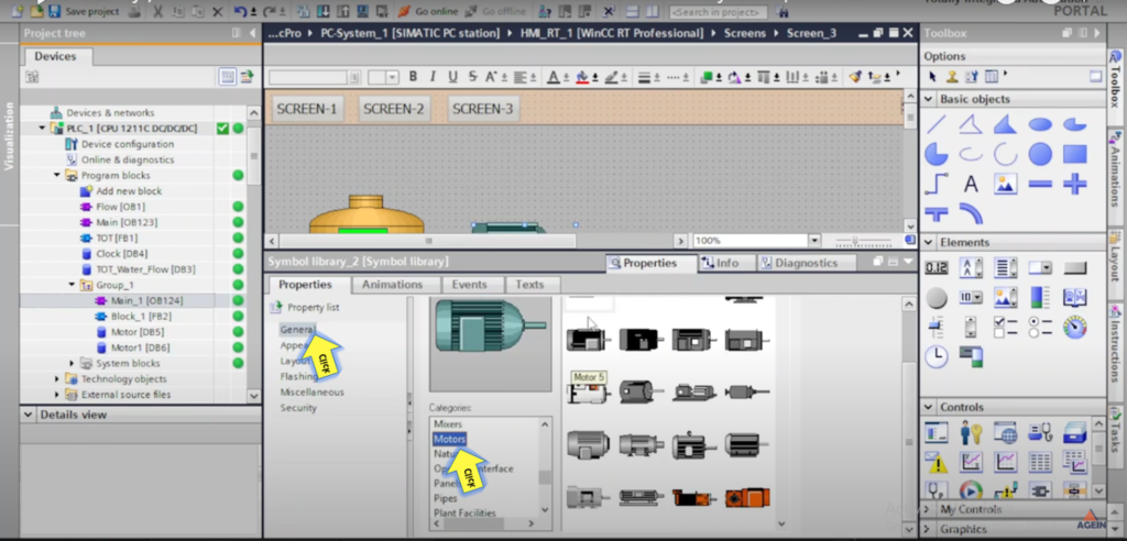
Step 8 :-
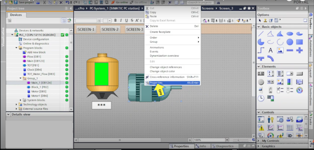
Right Click on “Motor” And
Select on “Properties”
Step 9 :-
Select Fill style “Shaded”
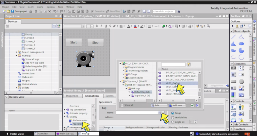
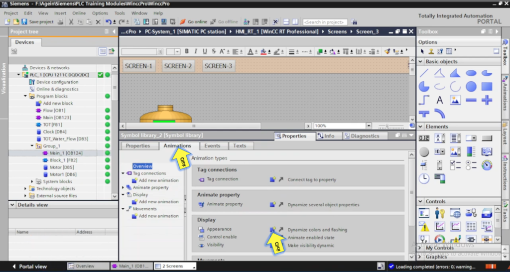
Step 10 :-
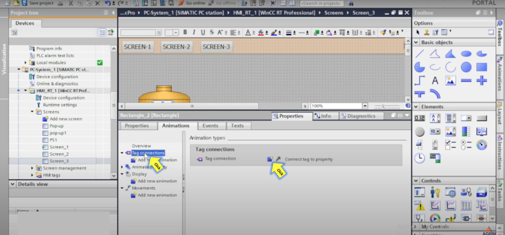
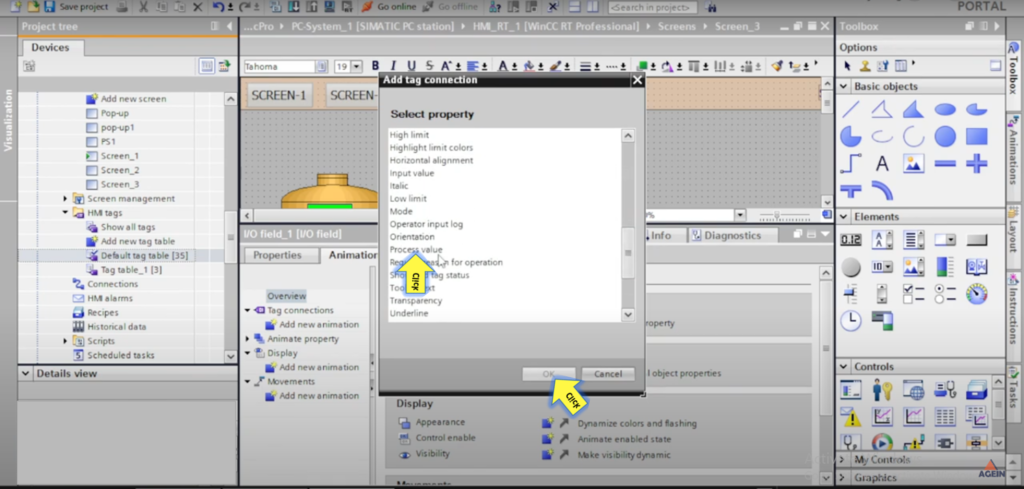
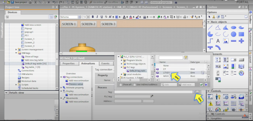
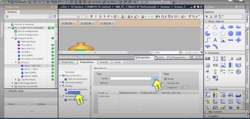
Click on “Appearance”
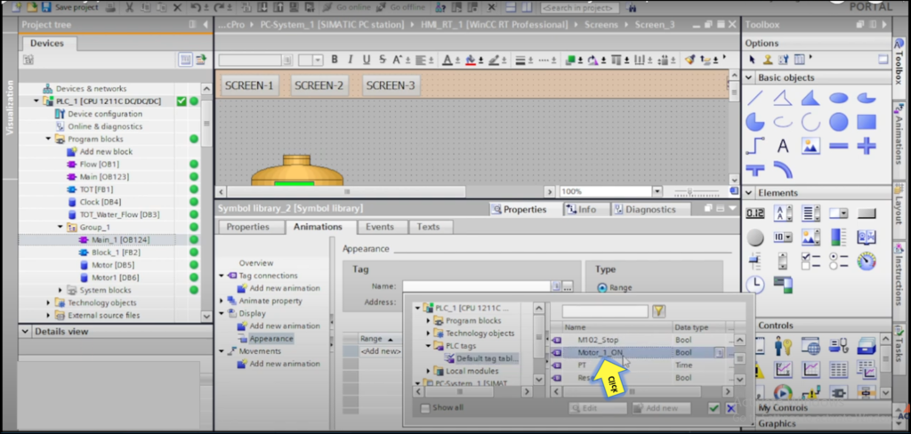
Click on ” Tag name”
Select Tag “M101_oncmd”
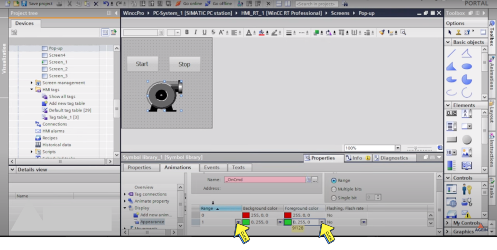
Step 11 :-
Select on “Range”
Select “Background Colour”
Select on “Foreground Colour”
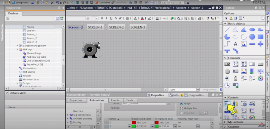
Step 12 :-
Select on ” Control”
Step 13 :-
Right Click on ” SCADA Screen” And
Select “Property”
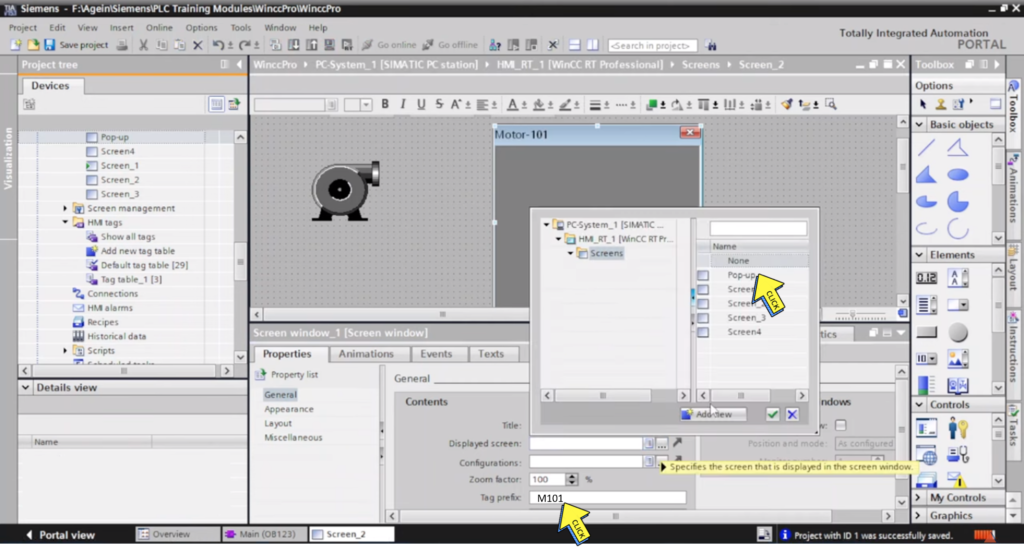
Step 14 :-
Check “Right Click”
Step 15 :-
Click on ” Displayed Screen”
Select Screen “Pop-up”
Fill the “Tag prefix”
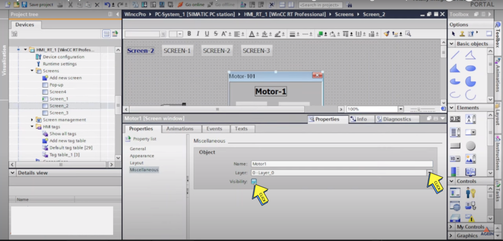
Step 16 :-
Click on “Miscellaneous”
Untick on “Visibility”
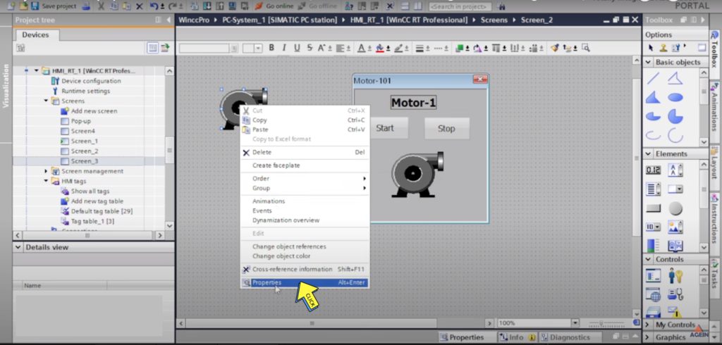
Step 17 :-
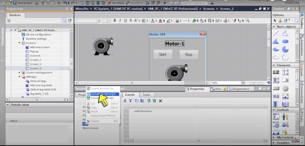
Right Click on “Motor”
Select on “Property”
Step 18 :-
Select on “Click”
Click on “Convert to VB Script ”
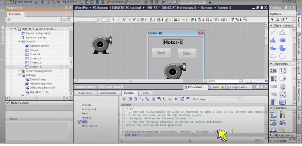
Step 19 :-
Type the
Set Property By Constant Accesspath “Motor, visible”
Step 20 :-
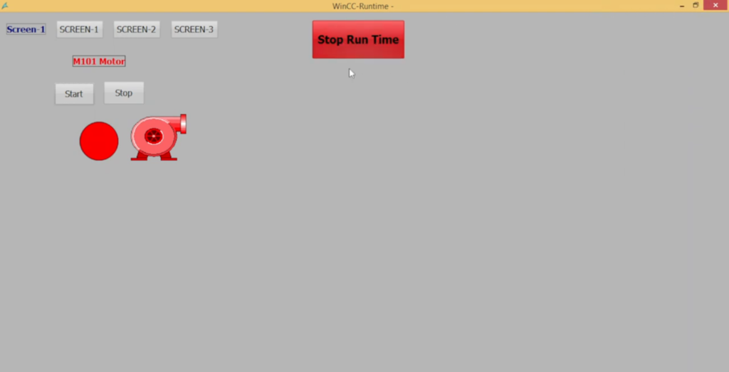
“Pop up Window “
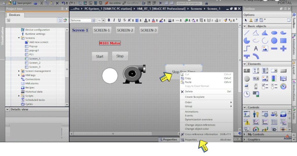
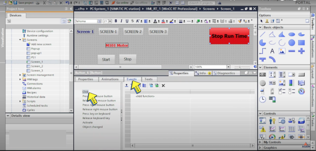
How to Stop RunTime or Deactivate Wincc RT Professional Running SCADA Application?
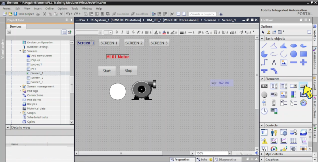
Step 1 :-
Select on “Button”
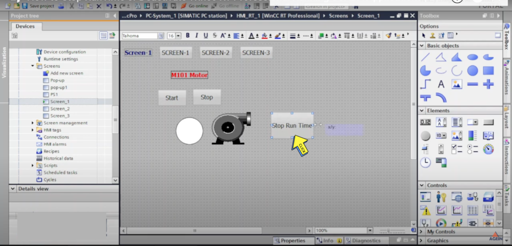
Step 2 :-
Fill the Name “Stop Run time”
Step 3 :-
Right Click “Button”
Select on “Properties”
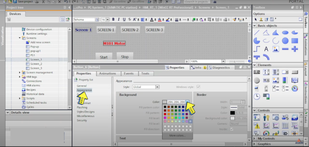
Step 4 :-
Click on “Appearance”
Select the ” Background Colour”
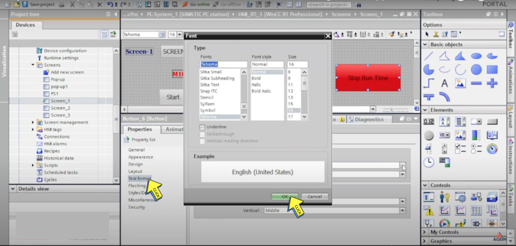
Step 5 :-
Click on “Text Format”
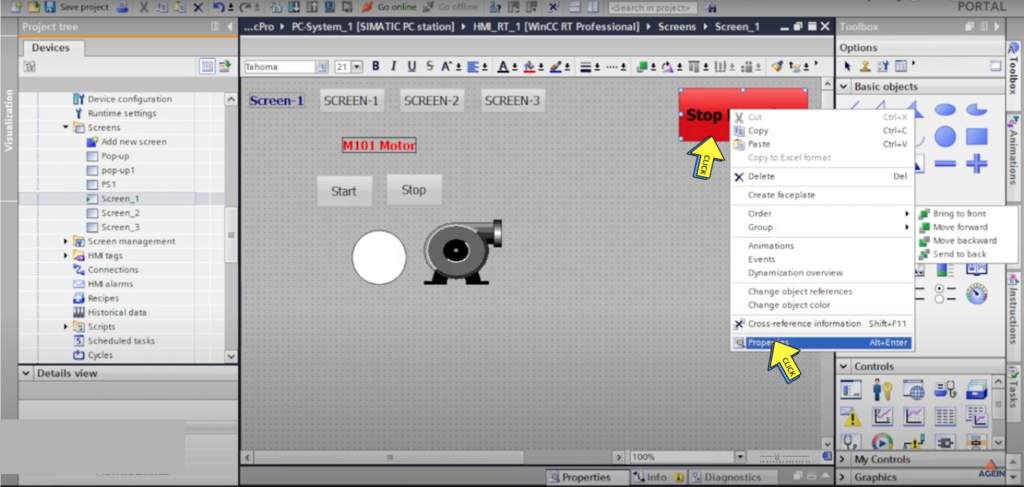
Step 6 :-
Right Click on “Button”
Select on “properties”
Step 7 :-
Click on “Button”
Select on “Click”
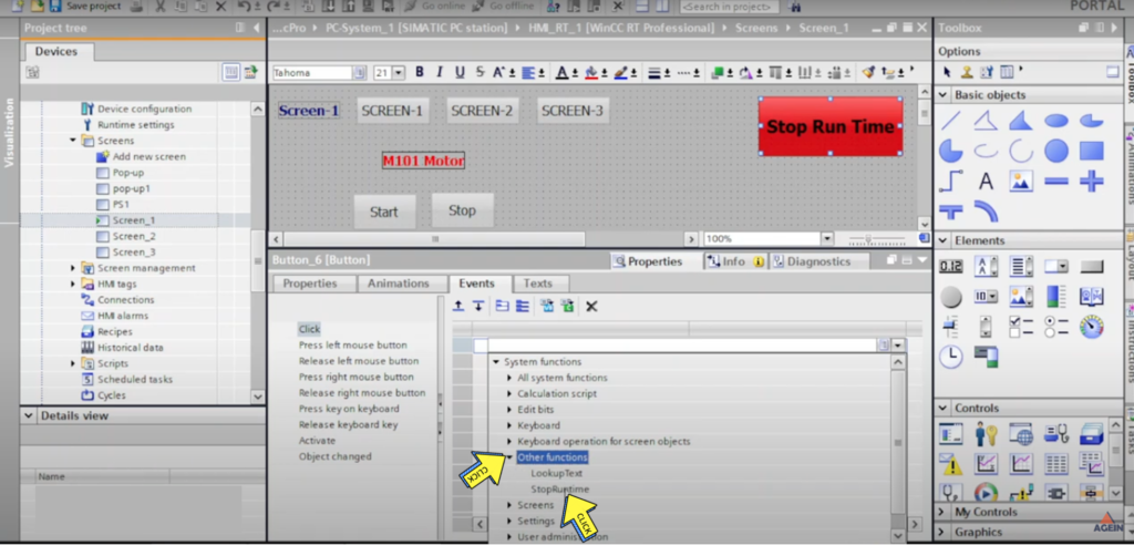
Step 8 :-
Click on “Events”
Select on “Click”
Step 9 :-
Click on “Other Functions”
Select on “Stop Run time”
Step 10 :-
Created “Stop Run Time” button
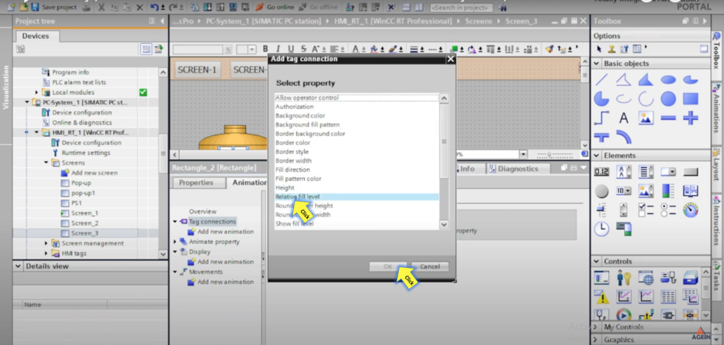
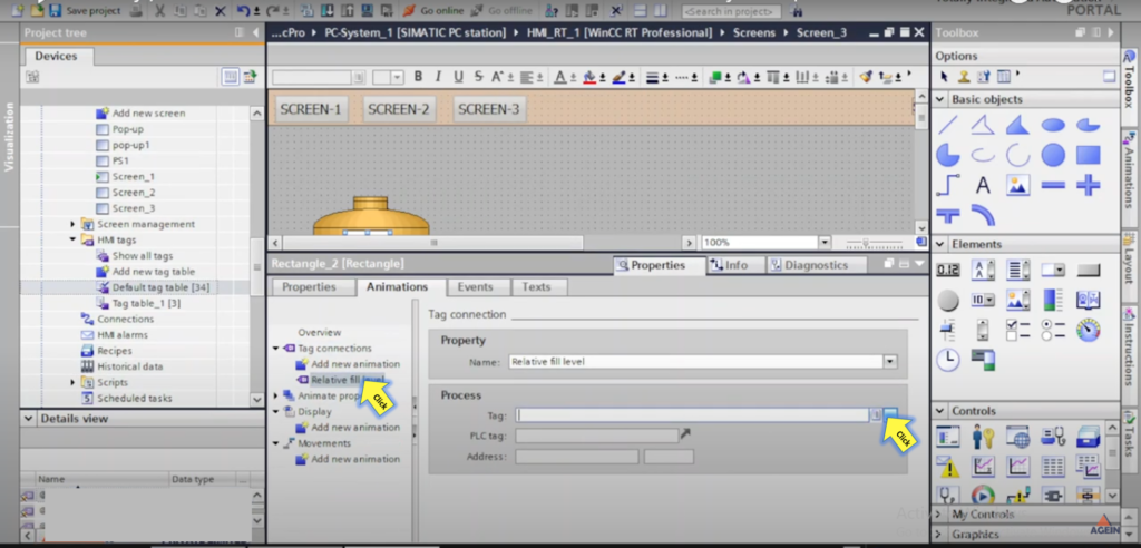
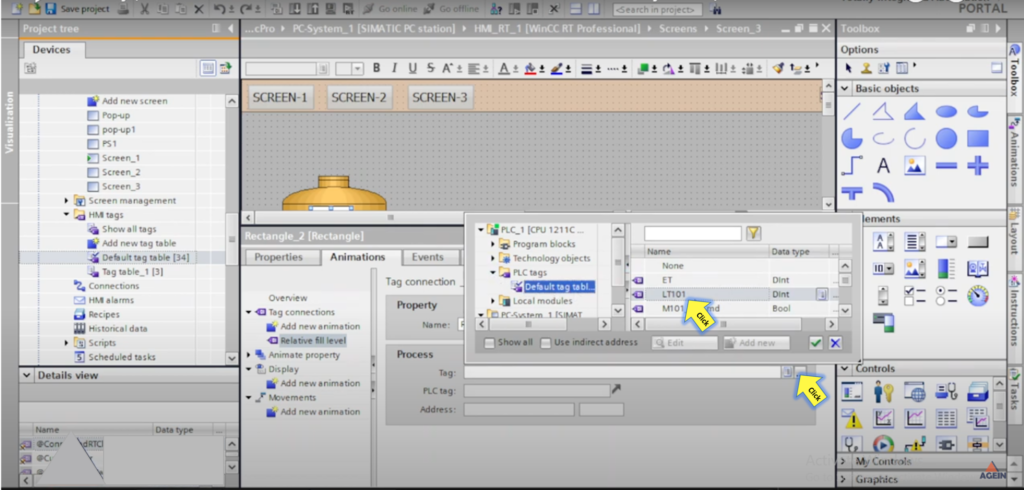
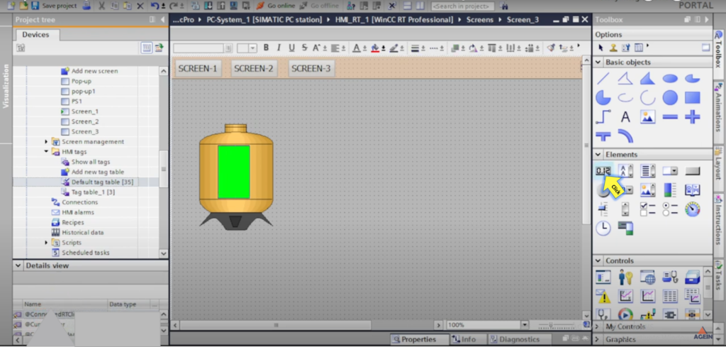
Visibility , Colour & Fill Animation in WinCC Professional RT SCADA System