Section8:Program/Operator Control Instructions
Totalizer (TOT)
The TOT instruction provides a time – scaled accumulation of an analog input value.
Input Parameter
- In1
- TimeBase
ProgProgReq
ProgoperReq
ProgStartReq
ProgStopReq
ProgResetReq
Description
- The analog signal input to the instruction. Valid = any float Default = 0.0
- The timebase input. The time base of the totalization based on the In engineering units.
- value Description
- 0 Second
- 1 Minutes
- 2 Hours
- 3 Days
- Program program request. Set to request Program control. Ignored if ProgOperReq is set. Holding this and set and ProgOperReq cleared locks the instruction in program control. Default is cleared.
- Prograam Operatort Request. Set to request Operator control. Holding this set locks the instruction in Operator control. Default is cleared.
- The program start request input. Set to request totalization to start. Default is cleared.
- The program stop request input. Set to request totalization to stop. Default is cleared.
- The program reset request input. Set to request the Total to reset to the ResetValue. Default is cleared.
Output Parameter:
- Total
- OldTotal
- ProgOper
- RunStop
ProgResetDone
TargetFlag TargetDev1Flag TargetDev2flag
Description:
- The totalized value if In. Arithmetic status flags are set for this output.
- The value of the total before a reset occurred. You can monitor this value to read the exact total just before the last reset.
- program/operator control indicator. Set when in program control. cleared when in operator control.
- The indicator of the operational state of the totalizer. Set when the TOT instruction is running. Cleared when the TOT instruction is stopped.
- The indicator that the TOT instruction has completed a program reset request. Set when the instruction resets as a result of ProgResetReq. You can monitor this to determine that a reset successfully completed. Cleared when ProgResetReq is cleared.
- The flag for Total. Set when Total ³ Target.
- The flag for TargetDev1. Set when Total ³ Target – TargetDev1
- The flag for TargetDev2. Set when Total ³ Target – TargetDev2
Example
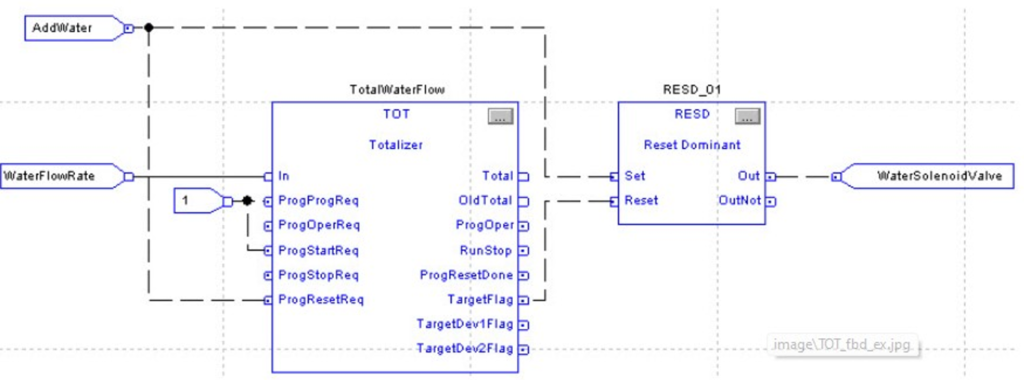
In this example, the TOT instruction meters a target quantity of water into a tank and shuts off the flow once the proper amount of water has been added. When the AddWater pushbutton is pressed, the TOT instruction resets and starts totalizing the amount of water flowing into the tank. Once the Target value is reached, the TOT instruction sets the TargetFlag output, which causes the solenoid valve to close. For this example, the TOT instruction was “locked” into Program Run by setting the ProgProgReq and ProgStartReq inputs. This is done for this example because the operator never needs to directly control the TOT instruction.
Enhanced PID (PIDE)
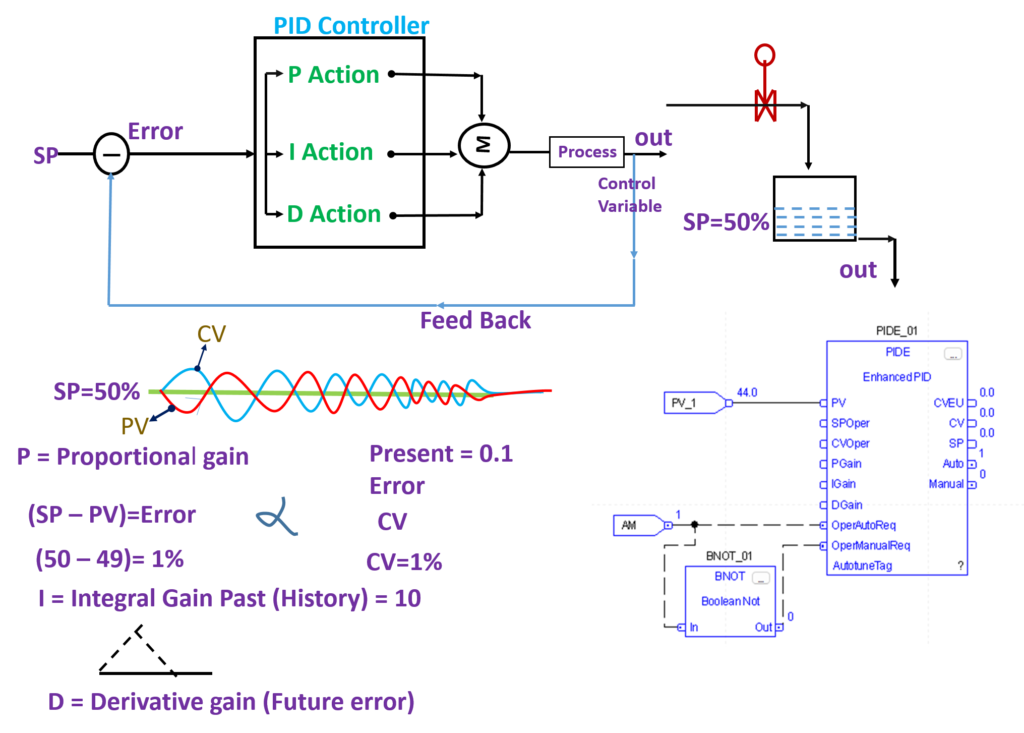
The PIDE instruction provides enhanced capabilities over the standard PID instruction. The instruction uses the velocity form of the PID algorithm. The gain terms are applied to the change in the value of error or PV, not the value of error or PV.
Input Parameter:
- PV
- SP Prog
SPCascade
RatioProg
CVProg
ff
ProgProgReq
ProgOperReq
ProgCasRatReq
ProgAutoReq
ProgManualReq
ProgOverridereq
ProgHandReq
Description:
- The scaled analog temperature signal input to the instruction. Valid = any float Default = 0.0
- SP program value, scaled in PV units. SP is set to this value when in Program control and not Cascade/Ratio mode. If the value of SPProg < SPLLimit or > SPHLimit, the instruction sets the appropriate bit in Status and limits the value used for SP. Valid = SPLLimit to SPHLimit Default = 0.0
- SP Cascade value, scaled in PV units. If CascadeRatio is set and UseRatio is cleared, then SP = SPCascade. This is typically the CVEU of a primary loop. If CascadeRatio and UseRatio are set, then SP = (SPCascade x Ratio). If the value of SPCascade < SPLLimit or > SPHLimit, set the appropriate bit in Status and limit the value used for SP. Valid = SPLLimit to SPHLimit Default = 0.0
- Ratio program multiplier. Ratio and RatioOper are set equal to this value when in Program control. If RatioProg < RatioLLimit or > RatioHLimit, the instruction sets the appropriate bit in Status and limits the value used for Ratio. Valid = RatioLLimit to RatioHLimit Default = 1.0
- CV program manual value. CV equals this value when in Program Manual mode. If CVProg < 0 or > 100, or < CVLLimit or > CVHLimit when CVManLimiting is set, the instruction sets the appropriate bit in Status and limits the CV value. Valid = 0.0 to 100.0 Default = 0.0
- Feed forward value. The value of feed forward is summed with CV after the zero-crossing deadband limiting has been applied to CV. Therefore changes in FF are always reflected in the final output value of CV. If FF < -100 or > 100, the instruction sets the appropriate bit in Status and limits the value used for FF. Valid = -100.0 to 100.0 Default = 0.0
- Program program request. Set by the user program to request Program control. Ignored if ProgOperReq is set. Holding this set and ProgOperReq cleared locks the instruction in Program control. When ProgValueReset is set, the instruction clears the input each execution. Default is cleared.
- Program operator request. Set by the user program to request Operator control. Holding this set locks the instruction in Operator control. When ProgValueReset is set, the instruction clears the input each execution. Default is cleared.
- Program cascade/ratio mode request. Set by the user program to request Cascade/Ratio mode. When ProgValueReset is set, the instruction clears the input each execution. Default is cleared
- Program auto mode request. Set by the user program to request Auto mode. When ProgValueReset is set, the instruction clears the input each execution. Default is cleared
- Program manual mode request. Set by the user program to request Manual mode. When ProgValueReset is set, the instruction clears the input each execution. Default is cleared
- Program override mode request. Set by the user program to request Override mode. When ProgValueReset is set, the instruction clears the input each execution. Default is cleared
- Program hand mode request. Set by the user program to request Hand mode. This value is usually read as a digital input from a hand/auto station. When ProgValueReset is set, the instruction clears the input each execution. Default is cleared.
Output Parameter:
- SP
- ProgOper
- CasRat
- Auto
- manual
- Override
- Hand
- DevHHAlarm
- DevHAlarm
- DevLAlarm
- DevLLAlarm
- CVEU
13.CV
Description:
- Current setpoint value. The value of SP is used to control CV when in Auto or Cascade/ Ratio mode.
- Program/operator control indicator. Set when in Program control. Cleared when in Operator control
- Cascade/ratio mode indicator. Set when in the Cascade/Ratio mode.
- Auto mode indicator. Set when in the Auto mode.
- Manual mode indicator. Set when in the Manual mode.
- Override mode indicator. Set when in the Override mode.
- Hand mode indicator. Set when in the Hand mode.
- Deviation high-high alarm indicator. Set when PV (SP + DevHHLimit). Cleared when PV < (SP + DevHHLimit – DevDeadband)
- Deviation high alarm indicator. Set when PV (SP + DevHLimit). Cleared when PV < (SP + DevHLimit – DevDeadband)
- Deviation low alarm indicator. Set when PV (SP – DevLLimit). Cleared when PV > (SP – DevLLimit + DevDeadband)
- Deviation low-low alarm indicator. Set when PV (SP – DevLLLimit). Cleared when PV > (SP – DevLLLimit + DevDeadband)
- using CVEUMax and CVEUMin, where CVEUMax corresponds to 100 percent and CVEUMin corresponds to 0 percent. This output typically controls an analog output module or a secondary loop. Arithmetic flags are set for this output. CVEU = (CV x CVEUSpan / 100) + CVEUMin CVEU span calculation: CVEUSpan = (CVEUMax – CVEUMin)
- expressed as 0 to 100 percent. CV is limited by CVHLimit and CVLLimit when in auto or cascade/ratio mode or manual mode if CVManLimiting is set. Otherwise this value is limited by 0 and 100 percent. Arithmetic flags are set for this output.
Example :
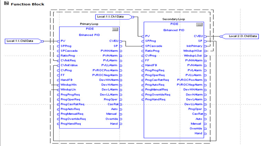
Cascade control is useful when externally-caused upsets to the controlled variable occur often, which then cause upsets to the process variable you are trying to control. For example, try to control the temperature of liquid in a tank by varying the amount of steam fed into a heating jacket around the tank. If the steam flow suddenly drops because of an upstream process, the temperature of the liquid in the tank eventually drops and the PIDE instruction then opens the steam valve to compensate for the drop in temperature
In this example, a cascaded loop provides better control by opening the steam valve when the steam flow drops before the liquid temperature in the tank drops. To implement a cascaded loop, use a PIDE instruction to control the steam valve opening based on a process variable signal from a steam flow transmitter. This is the secondary loop of the cascaded pair. A second PIDE instruction (called the primary loop) uses the liquid temperature as a process variable and sends its CV output into the setpoint of the secondary loop. In this manner, the primary temperature loop asks for a certain amount of steam flow from the secondary steam flow loop. The steam flow loop is then responsible for providing the amount of steam requested by the temperature loop in order to maintain a constant liquid temperature.
Ramp/Soak (RMPS)
The RMPS instruction provides for a number of segments of alternating ramp and soak periods.
Input Parameter:
- PV
- CurrentSegProg
OutProg
SoakTimeProg
ProgProgReq
ProgOperReq
ProgAutoReq
ProgManualReq
ProgHoldReq
Description:
- The scaled analog temperature signal input to the instruction. Valid = any float Default = 0.0
- Current segment program. The user program writes a requested value for the CurrentSeg into this input. This value is used if the ramp/soak is in Program Manual mode. If this value is invalid, the instruction sets the appropriate bit in Status. Valid = 0 to NumberOfSegs-1 Default = 0
- Output program. The user program writes a requested value for the Out into this input. This value is used as the Out when the ramp/soak is in Program Manual mode. Valid = any float Default = 0.0
- Soak time program. The user program writes a requested value for the SoakTimeLeft into this input. This value is used if the ramp/soak is in Program Manual mode. If this value is invalid, the instruction sets the appropriate bit in Status. Valid = 0.0 to maximum positive float Default = 0.0
- Program program request. Set by the user program to request program contreol. Ignored if ProgOperReq is set. Holding this set and ProgOperReq cleared locks the instruction in program control. Default is cleared.
- Program operator request. Set by the user program to request operator control. Holding this set locks the instruction in Operator control. Default is cleared.
- Program auto mode request. Set by the user program to request the ramp/soak to enter Auto mode. Ignored if the loop is in Operator control, if ProgManualReq is set, or if ProgHoldReq is set. Default is cleared.
- Program manual mode request. Set by the user program to request the ramp/soak to enter Manual mode. Ignored if the ramp/soak is in Operator control or if ProgHoldReq is set. Default is cleared.
- Program hold mode request. Set by the user program to request to stop the ramp / soak without changingthe Out, CurrentSeg, or SoakTimeLift. Also useful when a PID loop getting its setpoint from the ramp/soak leaves cascade. An operator can a ccomplish the same thing by placing the ramp/soak into Operator Manual mode. Default is cleared.
Output Parameter:
- Out
- CurrentSeg
- SoakTimeLeft
- ProgOper
- Auto
- manual
- Hold
- GuarRampOn
GuarSoakOn
Description:
- The output of the ramp/soak instruction. Arithmetic status flags are used for this output.
- Current segment number. Displays the current segment number in the ramp/soak cycle. Segments start numbering at 0.
- Soak time lift. Displays the soak time remaining for the current soak.
- Program/Operator control indicator. Set when in Program control Cleared when in Operator Control.
- Auto mode. Set when the ramp/soak is in Program Auto or Operator Auto mode.
- Manual mode. Set when the ramp/soak is in Program Manual Operator Manual mode.
- Hold mode. Set when the ramp/soak is in program Hold mode. Status of the function block.
- Guaranteed ramp status. Set if the Guaranteed Ramp feature is in use and the ramp is temporarily suspended because the PV differs from the output by more than the RampDeadband
- Guaranteed soak status. Set if the Guaranteed Soak feature is in use and the soak timer is cleared because the PV differs from the output by more than the SoakDeadband.
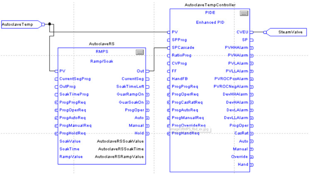
In this example, the RMPS instruction drives the setpoint of a PIDE instruction. When the PIDE instruction is in Cascade/Ratio mode, the output of the RMPS instruction is used as the setpoint. The PV to the PIDE instruction can be optionally fed into the PV input of the RMPS instruction if you want to use guaranteed ramping and/or guaranteed soaking.
In this example, the AutoclaveRSSoakValue, AutoclaveRSSoakTime, and AutoclaveRSRampValue arrays are REAL arrays with 10 elements to allow up to a 10 segment RMPS profile.
Function Generator (FGEN)
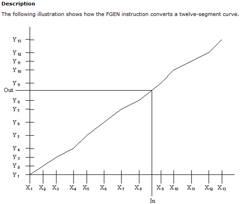
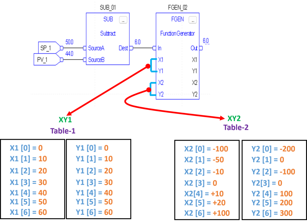
The FGEN instruction converts an input based on a piece-wise linear function.
Operand:
1.X1
2.Y1
3.X2
4.Y2
Description:
- X-axis array, table one. Combine with the Y-axis array, table one to define the points of the first piece-wise linear curve. Valid = any float
- Y-axis array, table one. Combine with the X-axis array, table one to define the points of the first piece-wise linear curve. Valid = any float
- (optional) X-axis array, table two. Combine with the Y-axis array, table two to define the points of the second piece-wise linear curve. Valid = any float
- (optional) Y-axis array, table two. Combine with the X-axis array, table two to define the points of the second piece-wise linear curve. Valid = any float
Input Parameter:
In
XY1Size
XY2Size
Select
Description:
The analog signal input to the instruction. Valid = any float Default = 0.0
Number of points in the piece-wise linear curve to use from table one. If the value is less than one and Select is cleared, the instruction sets the appropriate bit in Status and the output is not changed. Valid = 1 to (smallest of X1 and Y1 array sizes) Default = 1
Number of points in the piece-wise linear curve to use from table two. If the value is less than one and Select is set, the instruction sets the appropriate bit in Status and the output is not changed. Valid = 0 to (smallest of X2 and Y2 array sizes) Default = 0
This input determines which table to use. When cleared, the instruction uses table one; when set, the instruction uses table two. Default is cleared.
Input Parameter:
- OUT
- XY1SizeInv (Status.1)
- XY2SizeInv (Status.2)
Description:
- Output of the instruction. Arithmetic status flags are set for this output.
- Size of table 1 is invalid or not compatible with the array size
- Size of table 2 is invalid or not compatible with the array size.
