Use relay-type (bit) instructions to monitor and/or control bits in a data file or function file, such as input bits or timer control-word bits. The following instructions are described in this chapter:
Ladder Diagram
Function Block Diagram
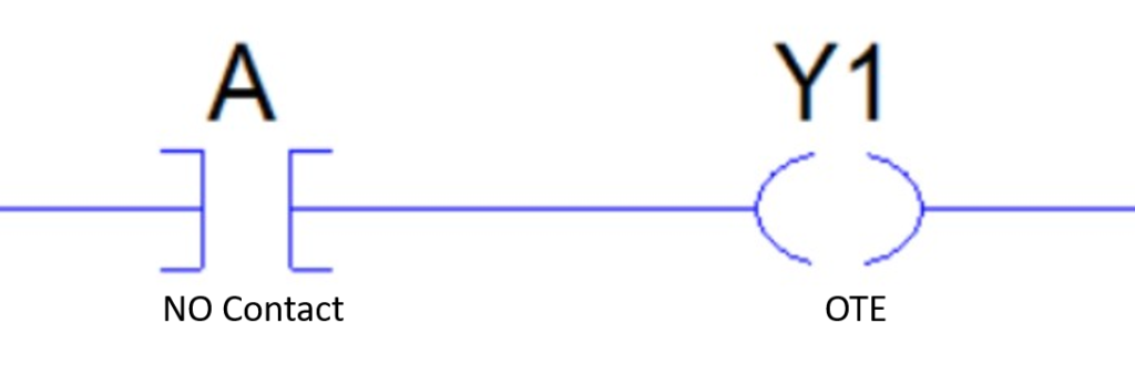
"NO" Contact logic
If input tag “A” is true than Output tag ‘Y1″ is true.
If Value Tag “A” Is Equal To 1 Than value Of Output Tag “Y1” is
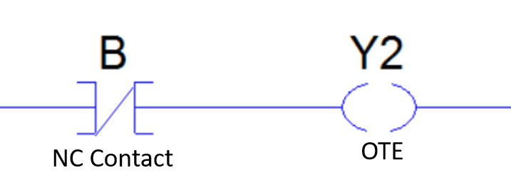
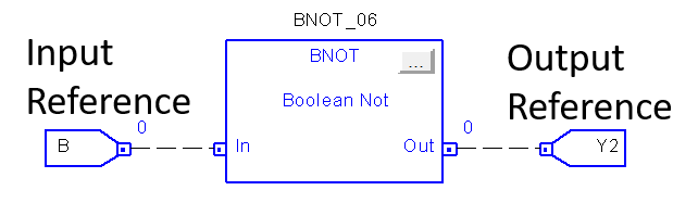
"NC" Contact Logic
If input tag “B” is true than Output tag ‘Y2″ is true.
If Value Tag “B” Is Equal To 1 Than value Of Output Tag “Y2” is
.
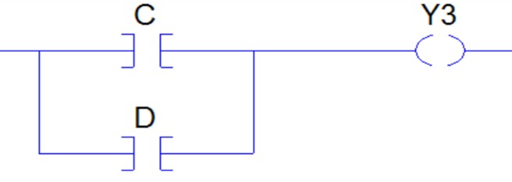
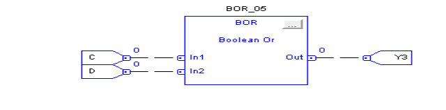
Boolean "OR" Gate logic
The OR gate gets its name from the fact that it behaves after the fashion of the logical inclusive “or.” The output is “true” if either or both of the inputs are “true.” If both inputs are “false,” then the output is “false.” In other words, for the output to be 1, at least input one OR two must be 1.
Boolean OR GATE
Boolean OR GATE
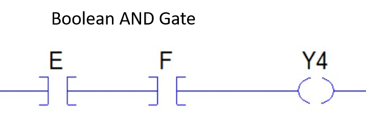
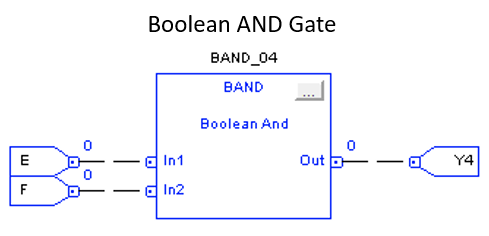
Boolean "AND" Gate logic
The AND gate is so named because, if 0 is called “false” and 1 is called “true,” the gate acts in the same way as the logical “and” operator. The following illustration and table show the circuit symbol and logic combinations for an AND gate. (In the symbol, the input terminals are at left and the output terminal is at right.) The output is “true” when both inputs are “true.” Otherwise, the output is “false.” In other words, the output is 1 only when both inputs one AND two are 1
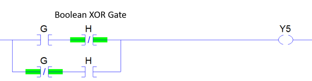
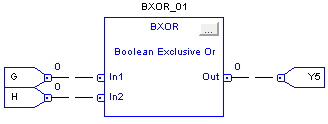
Boolean "XOR" Gate logic
The BXOR ( exclusive-OR ) gate acts in the same way as the logical “either/or.” The output is “true” if either, but not both, of the inputs are “true.” The output is “false” if both inputs are “false” or if both inputs are “true.” Another way of looking at this circuit is to observe that the output is 1 if the inputs are different, but 0 if the inputs are the same.
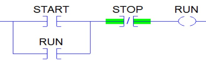
Motor Start Stop Logic
How to cunstruct a logic in ladder language for Motor start and stop using NO NC OTE ?
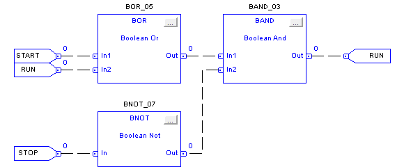
How to cunstruct a logic in FBD language for Motor start stop using BOR BAND BNOT ?
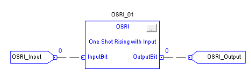
One Shot Rising with Input
(OSRI)
If InputBit is true, and it was false the last time the instruction was scanned then OutputBit will be set, otherwise OutputBit will be cleared.
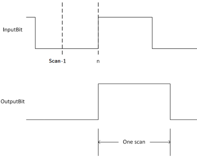
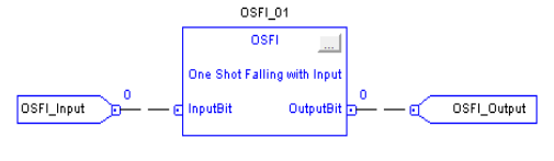
One Shot Falling with Input
(OSFI)
If InputBit is false, and it was true the last time the instruction was scanned then OutputBit will be set, otherwise OutputBit will be cleared.
Section-2:Timer and Counter Instructions
Use this instruction:
TONR
TOFR
RTOR
CTUD
If you want to:
time how long a timer is enabled with built-in reset in function block
time how long a timer is disabled with built-in reset in function block
accumulate time with built-in reset in function block
count up and count down in function block
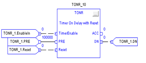
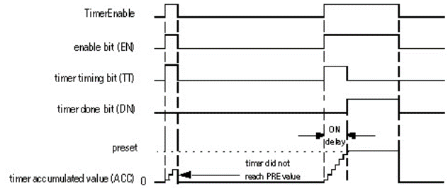
Timer On Delay with Reset(TONR)
When true, the TONR instruction accumulates time until the:
• TONR instruction is disabled • ACC> PRE
The time base is always 1 msec. For example, for a 2-second timer, enter 2000 for the PRE value.
Set the Reset input parameter to reset the instruction. If TimerEnable is set when Reset is true, the TONR instruction begins timing again when Reset is false.
How a Timer Runs
A timer runs by subtracting the time of its last scan from the current time:
• ACC = ACC + (current_time – last_time_scanned)
After it updates the ACC, the timer sets last_time_scanned= current_time. This gets the timer ready for the next scan.
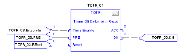
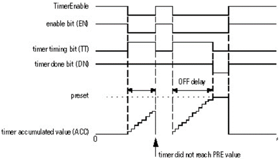
Timer Off Delay with Reset
(TOFR)
When true, the TOFR instruction accumulates time until the:
• TOFR instruction is disabled • ACC> PRE
The time base is always 1 msec. For example, for a 2-second timer, enter 2000 for the PRE value.
Set the Reset input parameter to reset the instruction. If TimerEnable is false when Reset is true, the TOFR instruction does not begin timing again when Reset is false..
How a Timer Runs
A timer runs by subtracting the time of its last scan from the current time:
ACC = ACC + (current_time – last_time_scanned) After it updates the ACC, the timer sets last_time_scanned= current_time. This gets the timer ready for the next scan.
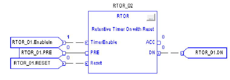
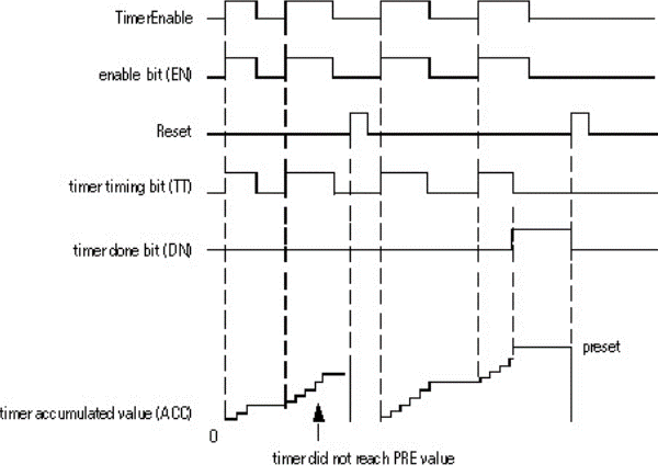
Retentive Timer On with
Reset (RTOR)
The RTOR instruction accumulates time until it is false. When the RTOR instruction is false, it retains its ACC value. You must clear the .ACC value using the Reset input.
The time base is always 1 msec. For example, for a 2-second timer, enter 2000 for the PRE value.
Set the Reset input parameter to reset the instruction. If TimerEnable is set when Reset is set, the RTOR instruction begins timing again when Reset is cleared.
How a Timer Runs
A timer runs by subtracting the time of its last scan from the current time:
• ACC = ACC + (current_time – last_time_scanned)
• After it updates the ACC, the timer sets last_time_scanned= current_time. This gets the timer ready for the next scan.
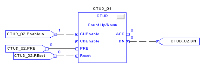
Count Up/Down (CTUD)
When true and CUEnable is true, the CTUD instructions increments the counter by one. When true and CDEnable is true, the CTUD instruction decrements the counter by one.
Both the CUEnable and CDEnable input parameters can be toggled during the same scan. The instruction executes the count up prior to the count down.
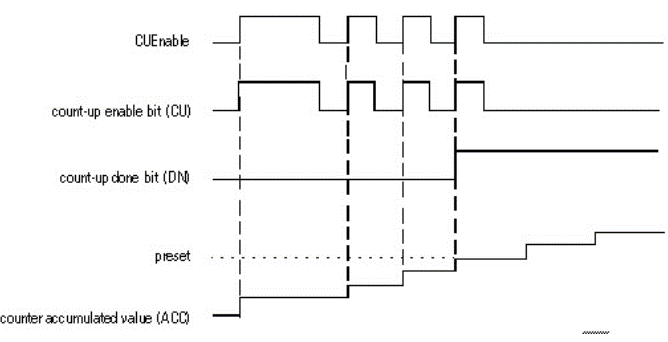
Count Up
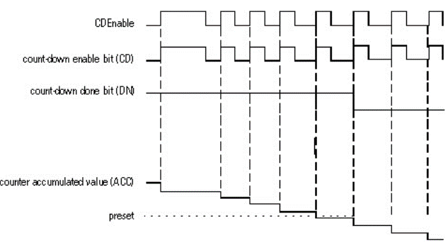
Count Down
When disabled, the CTUD instruction retains its accumulated value. Set the Reset input parameter to reset the instruction.
Section-3:Compare Instructions
Use this instruction:
EQU
GEQ
GRT
LEQ
LES
LIM
MEQ
NEQ
If you want to
test whether two values are equal
test whether one value is greater than or equal to a second value
test whether one value is greater than a second value
test whether one value is less than or equal to a second value
test whether one value is less than a second value
test whether one value is between two other values
pass two values through a mask and test whether they are equal
test whether one value is not equal to a second value
Compare values of different data types, such as floating point and integer.
The bold data types indicate optimal data types. An instruction executes at its fastest and with it lowest memory requirements if all the parameters of the instruction use the same optimal data type, typically DINT or REAL.
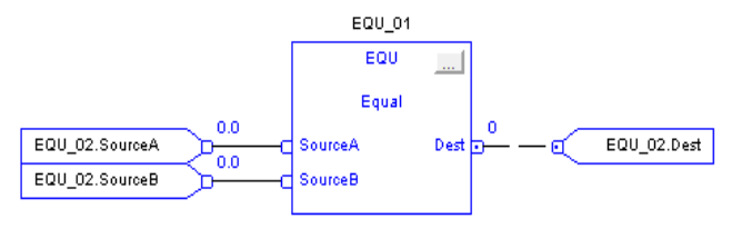
Equal To (EQU)
When enabled, the EQU instruction and the operator = test whether Source A is equal to Source B.
EQU Flow Chart (True)
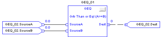
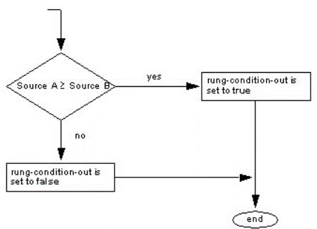
Greater Than or Equal To
(GEQ)
When enabled, the GEQ instruction and the operator >= test whether Source A is greater than or equal to Source B.
GEQ Flow Chart (True)
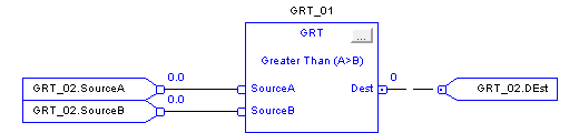
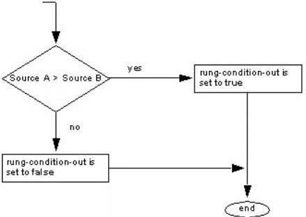
Greater Than (GRT)
When enabled, the GRT instruction and the operator > tests whether Source A is greater than Source B.
GRT Flow Chart (True)
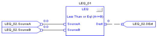
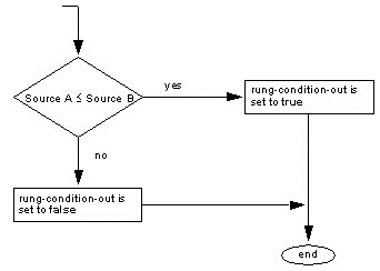
Less Than or Equal To (LEQ)
When enabled, the LEQ instruction and the operator <= tests whether Source A is less than or equal to Source B.
LEQ Flow Chart (True)
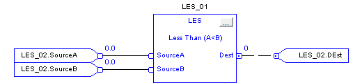
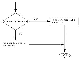
Less Than (LES)
When enabled, the LES instruction and the operator < tests Source A is less than Source B.
LES Flow Chart (True)
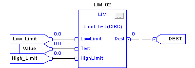
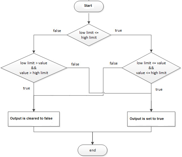
Limit (LIM)
The LIM instruction tests if the Test value is within the range of the Low and High Limits as indicated in the LIM Flow Chart (True).
If any operand is Not A Number (NAN), the .EnableOut is cleared to false.
LIM Flow Chart (True)
Example: Low Limit <= High Limit
When Test value is equal to or greater than Low Limit, and Test value is less than or equal to High Limit, light_1 is set.
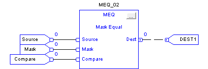
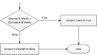
Mask Equal To (MEQ)
The MEQ instruction passes the Source and Compare values through a Mask and compares the results.
MEQ Flow Chart (True)
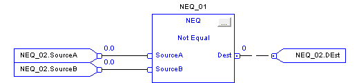
Not Equal To (NEQ)
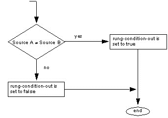
When enabled, the NEQ instruction and the <> operator tests whether Source A is not equal to Source B.
NEQ Flow Chart (True)
Section-4:Compute/Math Instructions
Use this instruction:
ADD
SUB
MUL
DIV
MOD
SQR
NEQ
ABS
If you want to
add two values
subtract two values
multiply two values
divide two values
determine the remainder after one value is divided by another
calculate the square root of a value
take the opposite sign of a value
take the absolute value of a value
You can mix data types, but loss of accuracy and rounding error might occur and the instruction takes more time to execute. Check the S:V bit to see whether the result was truncated.
The bold data types indicate optimal data types. An instruction executes faster and requires less memory if all the operands of the instruction use the same optimal data type, typically DINT or REAL.
A compute/math instruction executes once each time the instruction is scanned as long as the rung-condition-in is true. If you want the expression evaluated only once, use any one-shot instruction to trigger the instruction.
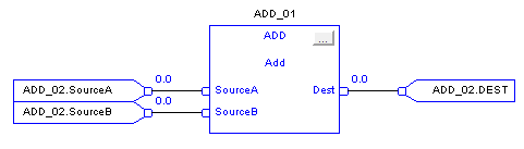
Add (ADD)
When enabled, the ADD instruction and the operator ‘+’ adds Source A to Source B.
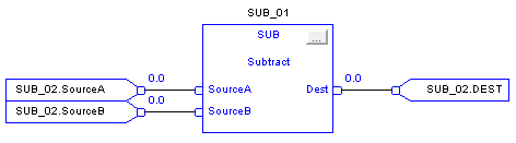
Subtract (SUB)
When enabled, the SUB instruction and the operator ‘-‘ subtracts Source B from Source A.
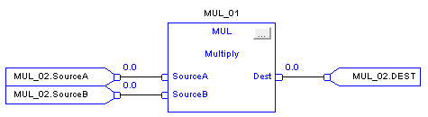
Multiply (MUL)
When enabled, the MUL instruction and the operator ‘*’ multiplies Source A with Source B.
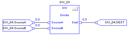
Divide (DIV)
When enabled, the DIV instruction and the operator ‘/’ divides Source A by Source B.
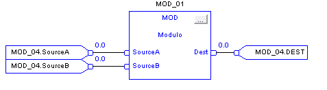
Modulo (MOD)
When enabled, the MOD instruction and the operator divides Source A by Source B and places the remainder in Dest. This is done using the algorithm:
Dest = Source A – (truncate ( Source A / Source B) * Source B)
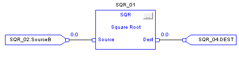
Square Root (SQR)
The SQR instruction and operator computes the square root of the Source and places the result in Dest.
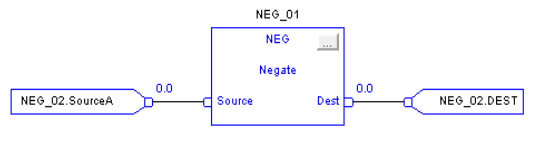
Negate (NEG)
When enabled, the NEG instruction and operator subtract the Source value from zero.
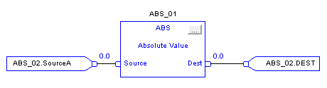
Absolute Value (ABS)
When enabled, the ABS instruction and operator take the absolute value of Source. The instruction stores the result in Dest while the operator simply returns the result. An overflow is indicated if the result is the maximum negative integer value, e.g. -128 for SINT, -32,768 for INT and -2,147,483,648 for DINT.
Section-5:Move/Logical Instruction
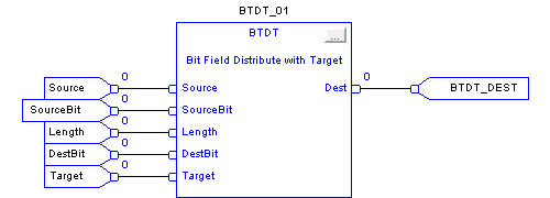
Bit Field Distribute with
Target (BTDT)
The BTDT instruction first copies the Target to the Destination. Then the instruction copies the specified bits from the Source, shifts the bits to the appropriate position, and writes the bits into the Destination. The Target and Source remain unchanged.
Section-6:Program Control Instructions
Use this instruction:
JSR
SBR
RET
If you want to
Jump to a separate routine, pass data to the routine, execute the routine, and return results.
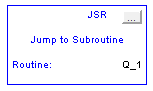
Jump to Subroutine (JSR),
The JSR instruction invokes another routine. When that routine completes, the execution returns to the JSR instruction.
Subroutine (SBR)
The SBR instruction receives the input parameters passed by the JSR.
Return (RET)
The RET instruction passes return parameters back to the JSR and ends the scan of the subroutine.
Section-7:Select/Limit Instructions
Use this instruction:
SEL
ESEL
SSUM
SNEG
MUX
HLL
RLIM
If you want to:
Select
Enhanced Select
Selected Summer
Selectable Negate
Multiplexer
High/Low Limit
Rate Limiter
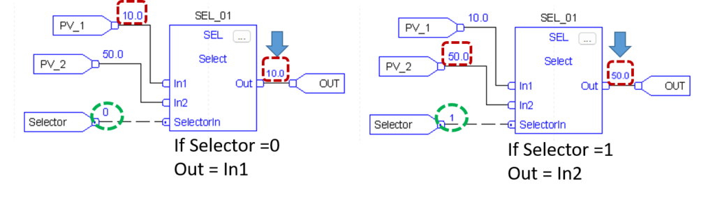
Select (SEL)
The SEL instruction uses a digital input to select one of two inputs.
Input Parameter
In1
In2
Selector In
Output Parameter
OUT
Description
The first analog signal input to the instruction. Valid =any float Default =0.0
The second analog signal input to the instruction. Valid = any float Default =0.0
The input that seletcts between In1 In2 . Default is Cleared.
Description
The calculated output of the algorithm.Arithmetic status flags are set for this output
Example:
The SEL instruction selects In1 or In2 based on SelectorIn . If SelectorIn is set, the instruction sets out = in2. If SelectorIn is Cleared, the instruction sets out = In1.
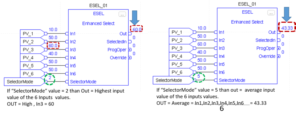
Enhanced Select (ESEL)
The ESEL instruction lets you select one of as many as six input. Selector options include :
manual select (either by operator o by program)
high select
low select
median select
average (mean) select
Input Parameter
In1
In2
In3
In4
In5
In6
Selector Mode
Description
The first analog signal input to the instruction. Valid =any float Default =0.0
The second analog signal input to the instruction. Valid = any float Default =0.0
The third analog signal input to the instruction. Valid = any float Default = 0.0
The fourth analog singnal input to the instruction. Valid = any float Default = 0.0
The fifth analog signal input to the instruction. Valid = any float Default = 0.0
The sixth analog signal input to the instruction. Valid = any float Default = 0.0
Selector mode input. This value determines the action of the instruction.
Value Description
manual
high select
low select
median select
average select
If this value is invalid, the instruction sets the appropriate bit in status and does not updete out. Valid = o to 4 Default =0
Output Parameter:
Out
SelectedIn
ProgOper
Override
Description:
The calculated output of the algorithm. Arithmetic status flags are set for this output.
Number of input selected. The instruction uses this value to display the number of the input currently being placed into the output. If the selector mode is average select, the instruction sets SelectedIn = 0.
Program/Operator control indicator. Set when in Program control. Cleared when in Operator control.
Override mode. Set when the instruction is in Override mode
Example
This ESEL instruction selects In1, In2, or In3,based on the SelectorMode. In this example, Selectormode = 1, Which means high select.The insturction determines which input value is the greatest and sets Out = greatest In
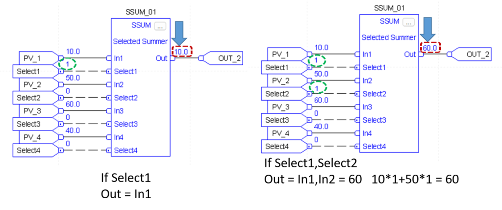
Selected Summer (SSUM)
The SSUM instruction uses Boolean inputs to select real inputs to be algebraically summed.
Input Parameter
In1
Select1
In2
Select2
In3
Select3
In4
Select4
Description
The first input to be summed. Valid = any float Default = 0.0
Selector signal for the first input. Default is Cleared.
The Second input to be summed. Valid = any float Default = 0.0
Selector signal for the second input Default is cleared.
The third input to be summed. Valid = any float Default = 0.0
Selector signal for the third input. Default is cleared.
The fourth input to be summed. Valid = any float Default = 0.0
Selector signal for the fourth input. Default is cleared.
Output Parameter:
Out
Description:
The calculated output of the algorithm.Arithmetic status flags are set for this ouput.,
Example
The value of select 2 determine whether to select analogInput1 and analog_input2, respectively. The instruction then adds the selected inputs and places the result in Out.
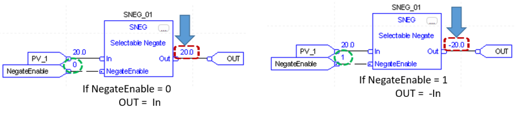
Selectable Negate (SNEG)
The SNEG instruction uses a digital input to select between the input value and negative of the input value.
Input Parameter
In
NegateEnable
Description
The analog signal input to the instruction. Valid = any float Default = 0.0
Negate enable. When NegateEnable is set, the instruction sets Out to the negative value of In. Default is set.
Output Parameter:
Out
Description:
The calculated output of the algorithm.Arithmetic status flags are set for this ouput.,
Example
The output determines whether to negate In or not. The instruction sets out = In if NegateEnable is set. Out becomes an input parameter
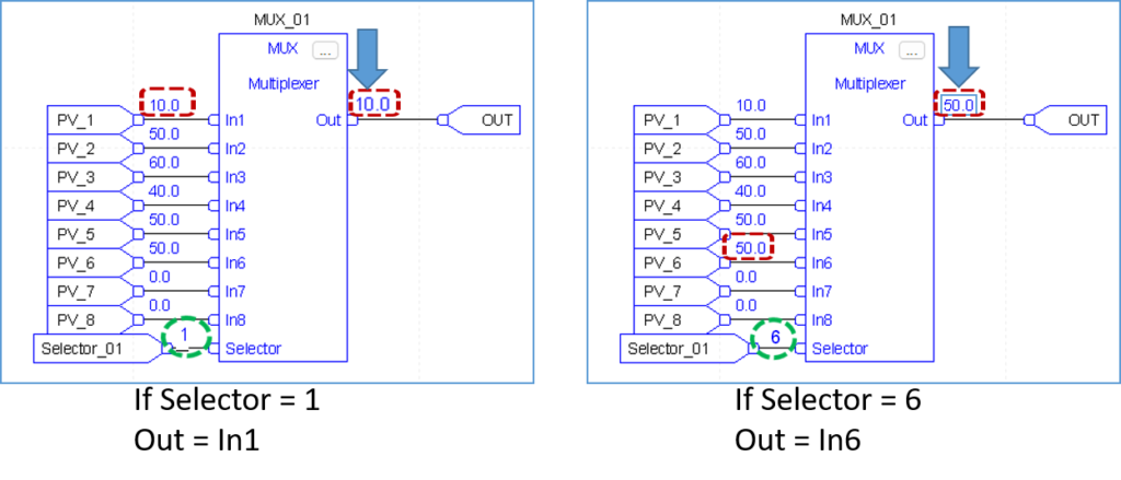
Multiplexer (MUX)
The MUX instruction selects one of eight inputs based on the selector input.
Input Parameter
In1
In2
In3
In4
In5
In6
In7
In8
Selector
Description
The first analog signal input to the instruction. Valid = any float Default = 0.0
The second analog signal input to the instruction. Valid = any float Default = 0.0
The third analog signal input to the instruction. Valid = any float Default = 0.0
The fourth analog signal input to the instruction. Valid = any float Default = 0.0
The fifth analog signal input to the instruction. Valid = any float Default = 0.0
The sixth analog signal input to the instruction. Valid = any float Default = 0.0
The seventh analog signal input to the instruction. Valid = any float Default = 0.0
The eighth analog signal input to the instruction. Valid = any float Default = 0.0
The selector input to the instruction. This input determines which of the inputs (1-8) is moved into Out. If this value is invalid (which includes 0), the instruction sets the appropriate bit in Status and holds Out at its current value. Valid = 1 to 8 Default = 0
Output Parameter:
Out
Description:
The selector output of the algorithm. Arithmetic status flags are set for this output.
Example
This MUX instruction selects In1, In2, In3, based on the Selector. The instruction sets Out = In which becomes an input an parameter for example , if value = 2, the instruction sets Out = analog _input2.
High / Low Limit (HLL)
The HLL instruction limits an analog input between two values. You can Select high/low,high,or low limits.
Input Parameter
In1
Description
The analog signal input to the instruction. Valid = any float Default = 0.0
Output Parameter:
Out
High Alarm
Low Alarm
Description:
The calculated output of the algorithm. Arithmetic status flags are set for this output.
The high alarm indicator. Set when In >= HighLimit.
The low alarm indicator. Set when In <= LowLimit
Example
This HLL instruction llimits In between two values and sets HighAlarm or LowAlarm, needed when In is outside the limits. The instruction sets Out = limited value of In, which becomes an input parameter for function_block_C.
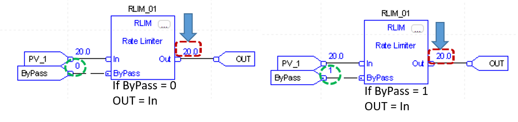
Rate Limiter (RLIM)
The RLIM instruction limits the amount of change of a signal over time.
Input Parameter
In1
By Pass
Description
The analog signal input to the instruction. Valid = any float Default = 0.0
Request to bypass the algorithm.when set, Out = In. Default is cleared.
Output Parameter:
Out
Description:
The calculated output of the algorithm. Arithmetic status flags are set for this output.
Example
The RLIM instruction limit In by IncRate . If analog_input1 changes at a rate greater than the IncRate value, the instruction limits In. The instruction sets Out = rate limited value of In, which becomes an input parameter for function_block_C.
Section8:Program/Operator Control Instructions
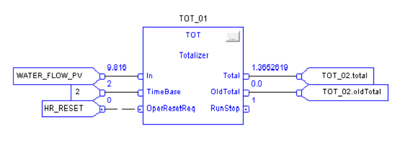
Totalizer (TOT)
The TOT instruction provides a time – scaled accumulation of an analog input value.
Input Parameter
In1
TimeBase
OperResetReq
Description
The analog signal input to the instruction. Valid = any float Default = 0.0
The timebase input. The time base of the totalization based on the In engineering units.
value Description
0 Second
1 Minutes
2 Hours
3 Days
The operator reset request input. Set by the operator interface to request totalization to reset. The instruction clears this input. Default is cleared.
Output Parameter:
Total
OldTotal
RunStop
Description:
The totalized value if In. Arithmetic status flags are set for this output.
The value of the total before a reset occurred. You can monitor this value to read the exact total just before the last reset.
The indicator of the operational state of the totalizer. Set when the TOT instruction is running. Cleared when the TOT instruction is stopped.
Example
In this example, the TOT instruction meters a target quantity of water into a tank and shuts off the flow once the proper amount of water has been added. When the AddWater pushbutton is pressed, the TOT instruction resets and starts totalizing the amount of water flowing into the tank. Once the Target value is reached, the TOT instruction sets the TargetFlag output, which causes the solenoid valve to close. For this example, the TOT instruction was “locked” into Program Run by setting the ProgProgReq and ProgStartReq inputs. This is done for this example because the operator never needs to directly control the TOT instruction.
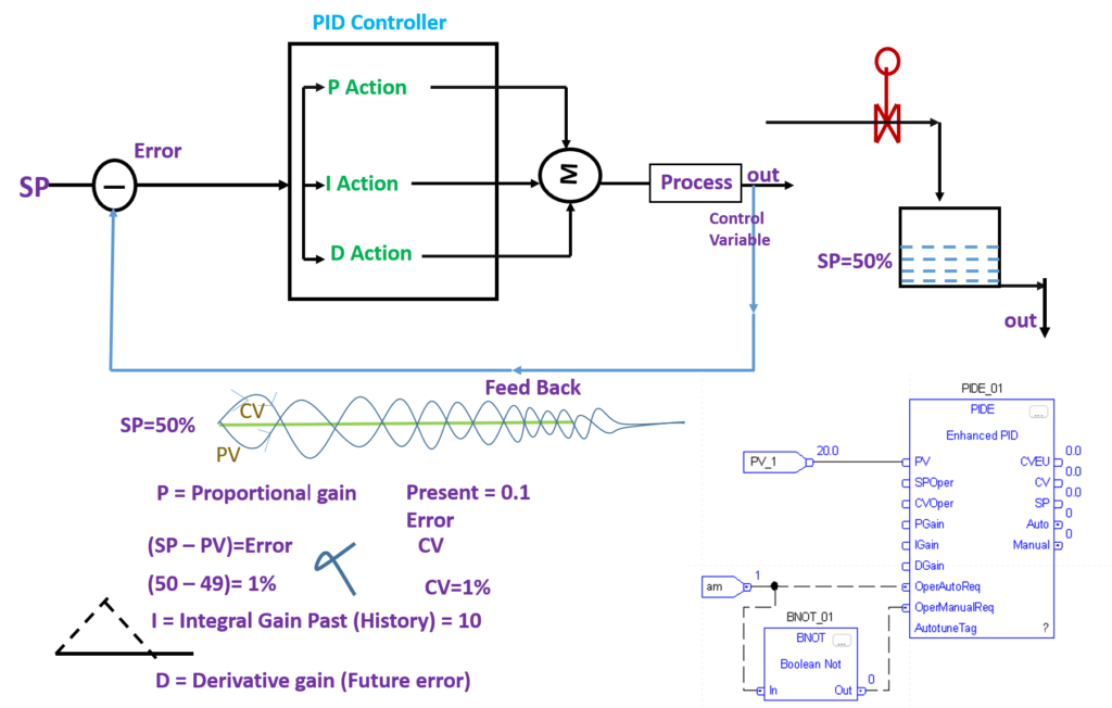
Enhanced PID (PIDE)
The PIDE instruction provides enhanced capabilities over the standard PID instruction. The instruction uses the velocity form of the PID algorithm. The gain terms are applied to the change in the value of error or PV, not the value of error or PV.
Input Parameter:
PV
SP Prog
SPCascade
RatioProg
CVProg
ff
ProgProgReq
ProgOperReq
ProgCasRatReq
ProgAutoReq
ProgManualReq
ProgOverridereq
ProgHandReq
Description:
The scaled analog temperature signal input to the instruction. Valid = any float Default = 0.0
SP program value, scaled in PV units. SP is set to this value when in Program control and not Cascade/Ratio mode. If the value of SPProg < SPLLimit or > SPHLimit, the instruction sets the appropriate bit in Status and limits the value used for SP. Valid = SPLLimit to SPHLimit Default = 0.0
SP Cascade value, scaled in PV units. If CascadeRatio is set and UseRatio is cleared, then SP = SPCascade. This is typically the CVEU of a primary loop. If CascadeRatio and UseRatio are set, then SP = (SPCascade x Ratio). If the value of SPCascade < SPLLimit or > SPHLimit, set the appropriate bit in Status and limit the value used for SP. Valid = SPLLimit to SPHLimit Default = 0.0
Ratio program multiplier. Ratio and RatioOper are set equal to this value when in Program control. If RatioProg < RatioLLimit or > RatioHLimit, the instruction sets the appropriate bit in Status and limits the value used for Ratio. Valid = RatioLLimit to RatioHLimit Default = 1.0
CV program manual value. CV equals this value when in Program Manual mode. If CVProg < 0 or > 100, or < CVLLimit or > CVHLimit when CVManLimiting is set, the instruction sets the appropriate bit in Status and limits the CV value. Valid = 0.0 to 100.0 Default = 0.0
Feed forward value. The value of feed forward is summed with CV after the zero-crossing deadband limiting has been applied to CV. Therefore changes in FF are always reflected in the final output value of CV. If FF < -100 or > 100, the instruction sets the appropriate bit in Status and limits the value used for FF. Valid = -100.0 to 100.0 Default = 0.0
Program program request. Set by the user program to request Program control. Ignored if ProgOperReq is set. Holding this set and ProgOperReq cleared locks the instruction in Program control. When ProgValueReset is set, the instruction clears the input each execution. Default is cleared.
Program operator request. Set by the user program to request Operator control. Holding this set locks the instruction in Operator control. When ProgValueReset is set, the instruction clears the input each execution. Default is cleared.
Program cascade/ratio mode request. Set by the user program to request Cascade/Ratio mode. When ProgValueReset is set, the instruction clears the input each execution. Default is cleared
Program auto mode request. Set by the user program to request Auto mode. When ProgValueReset is set, the instruction clears the input each execution. Default is cleared
Program manual mode request. Set by the user program to request Manual mode. When ProgValueReset is set, the instruction clears the input each execution. Default is cleared
Program override mode request. Set by the user program to request Override mode. When ProgValueReset is set, the instruction clears the input each execution. Default is cleared
Program hand mode request. Set by the user program to request Hand mode. This value is usually read as a digital input from a hand/auto station. When ProgValueReset is set, the instruction clears the input each execution. Default is cleared.
Output Parameter:
SP
ProgOper
CasRat
Auto
manual
Override
Hand
DevHHAlarm
DevHAlarm
DevLAlarm
DevLLAlarm
CVEU
13.CV
Description:
Current setpoint value. The value of SP is used to control CV when in Auto or Cascade/ Ratio mode.
Program/operator control indicator. Set when in Program control. Cleared when in Operator control
Cascade/ratio mode indicator. Set when in the Cascade/Ratio mode.
Auto mode indicator. Set when in the Auto mode.
Manual mode indicator. Set when in the Manual mode.
Override mode indicator. Set when in the Override mode.
Hand mode indicator. Set when in the Hand mode.
Deviation high-high alarm indicator. Set when PV (SP + DevHHLimit). Cleared when PV < (SP + DevHHLimit – DevDeadband)
Deviation high alarm indicator. Set when PV (SP + DevHLimit). Cleared when PV < (SP + DevHLimit – DevDeadband)
Deviation low alarm indicator. Set when PV (SP – DevLLimit). Cleared when PV > (SP – DevLLimit + DevDeadband)
Deviation low-low alarm indicator. Set when PV (SP – DevLLLimit). Cleared when PV > (SP – DevLLLimit + DevDeadband)
using CVEUMax and CVEUMin, where CVEUMax corresponds to 100 percent and CVEUMin corresponds to 0 percent. This output typically controls an analog output module or a secondary loop. Arithmetic flags are set for this output. CVEU = (CV x CVEUSpan / 100) + CVEUMin CVEU span calculation: CVEUSpan = (CVEUMax – CVEUMin)
expressed as 0 to 100 percent. CV is limited by CVHLimit and CVLLimit when in auto or cascade/ratio mode or manual mode if CVManLimiting is set. Otherwise this value is limited by 0 and 100 percent. Arithmetic flags are set for this output.
Example : 1
Example : 2
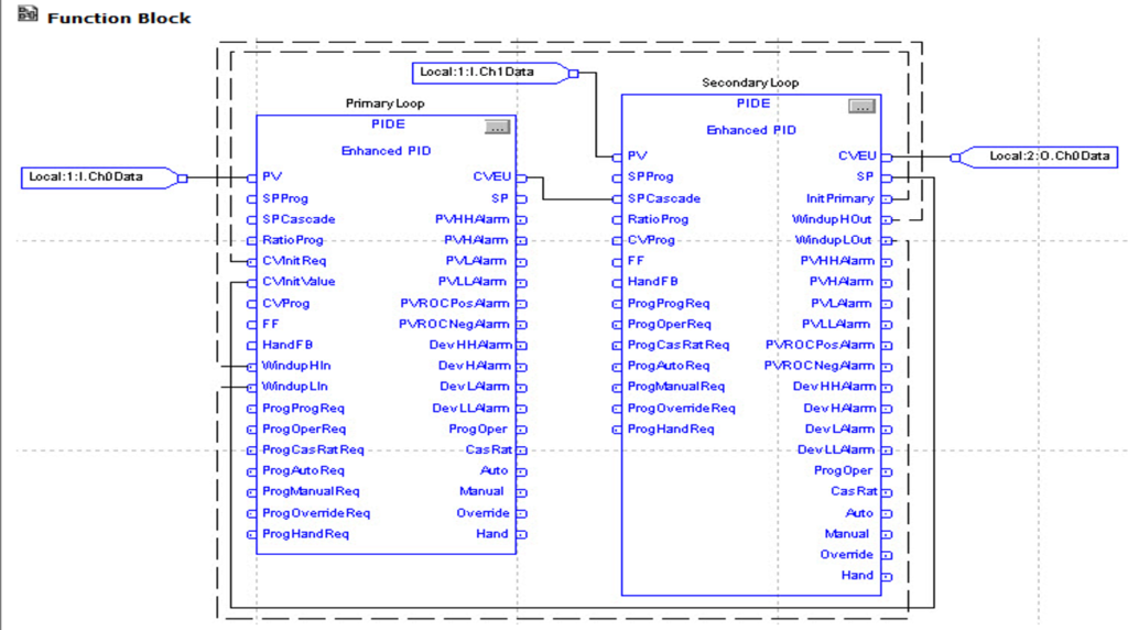
Cascade control is useful when externally-caused upsets to the controlled variable occur often, which then cause upsets to the process variable you are trying to control. For example, try to control the temperature of liquid in a tank by varying the amount of steam fed into a heating jacket around the tank. If the steam flow suddenly drops because of an upstream process, the temperature of the liquid in the tank eventually drops and the PIDE instruction then opens the steam valve to compensate for the drop in temperature
In this example, a cascaded loop provides better control by opening the steam valve when the steam flow drops before the liquid temperature in the tank drops. To implement a cascaded loop, use a PIDE instruction to control the steam valve opening based on a process variable signal from a steam flow transmitter. This is the secondary loop of the cascaded pair. A second PIDE instruction (called the primary loop) uses the liquid temperature as a process variable and sends its CV output into the setpoint of the secondary loop. In this manner, the primary temperature loop asks for a certain amount of steam flow from the secondary steam flow loop. The steam flow loop is then responsible for providing the amount of steam requested by the temperature loop in order to maintain a constant liquid temperature.
Ramp/Soak (RMPS)
The RMPS instruction provides for a number of segments of alternating ramp and soak periods.
Input Parameter:
PV
CurrentSegProg
OutProg
SoakTimeProg
ProgProgReq
ProgOperReq
ProgAutoReq
ProgManualReq
ProgHoldReq
Description:
The scaled analog temperature signal input to the instruction. Valid = any float Default = 0.0
Current segment program. The user program writes a requested value for the CurrentSeg into this input. This value is used if the ramp/soak is in Program Manual mode. If this value is invalid, the instruction sets the appropriate bit in Status. Valid = 0 to NumberOfSegs-1 Default = 0
Output program. The user program writes a requested value for the Out into this input. This value is used as the Out when the ramp/soak is in Program Manual mode. Valid = any float Default = 0.0
Soak time program. The user program writes a requested value for the SoakTimeLeft into this input. This value is used if the ramp/soak is in Program Manual mode. If this value is invalid, the instruction sets the appropriate bit in Status. Valid = 0.0 to maximum positive float Default = 0.0
Program program request. Set by the user program to request program contreol. Ignored if ProgOperReq is set. Holding this set and ProgOperReq cleared locks the instruction in program control. Default is cleared.
Program operator request. Set by the user program to request operator control. Holding this set locks the instruction in Operator control. Default is cleared.
Program auto mode request. Set by the user program to request the ramp/soak to enter Auto mode. Ignored if the loop is in Operator control, if ProgManualReq is set, or if ProgHoldReq is set. Default is cleared.
Program manual mode request. Set by the user program to request the ramp/soak to enter Manual mode. Ignored if the ramp/soak is in Operator control or if ProgHoldReq is set. Default is cleared.
Program hold mode request. Set by the user program to request to stop the ramp / soak without changingthe Out, CurrentSeg, or SoakTimeLift. Also useful when a PID loop getting its setpoint from the ramp/soak leaves cascade. An operator can a ccomplish the same thing by placing the ramp/soak into Operator Manual mode. Default is cleared.
Output Parameter:
Out
CurrentSeg
SoakTimeLeft
ProgOper
Auto
manual
Hold
GuarRampOn
GuarSoakOn
Description:
The output of the ramp/soak instruction. Arithmetic status flags are used for this output.
Current segment number. Displays the current segment number in the ramp/soak cycle. Segments start numbering at 0.
Soak time lift. Displays the soak time remaining for the current soak.
Program/Operator control indicator. Set when in Program control Cleared when in Operator Control.
Auto mode. Set when the ramp/soak is in Program Auto or Operator Auto mode.
Manual mode. Set when the ramp/soak is in Program Manual Operator Manual mode.
Hold mode. Set when the ramp/soak is in program Hold mode. Status of the function block.
Guaranteed ramp status. Set if the Guaranteed Ramp feature is in use and the ramp is temporarily suspended because the PV differs from the output by more than the RampDeadband
Guaranteed soak status. Set if the Guaranteed Soak feature is in use and the soak timer is cleared because the PV differs from the output by more than the SoakDeadband.
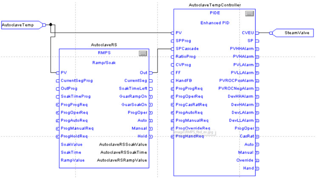
In this example, the RMPS instruction drives the setpoint of a PIDE instruction. When the PIDE instruction is in Cascade/Ratio mode, the output of the RMPS instruction is used as the setpoint. The PV to the PIDE instruction can be optionally fed into the PV input of the RMPS instruction if you want to use guaranteed ramping and/or guaranteed soaking.
In this example, the AutoclaveRSSoakValue, AutoclaveRSSoakTime, and AutoclaveRSRampValue arrays are REAL arrays with 10 elements to allow up to a 10 segment RMPS profile.