Section-7:Select/Limit Instructions
Use this instruction:
- SEL
- ESEL
- SSUM
- SNEG
- MUX
- HLL
- RLIM
If you want to:
- Select
- Enhanced Select
- Selected Summer
- Selectable Negate
- Multiplexer
- High/Low Limit
- Rate Limiter
Select (SEL)
The SEL instruction uses a digital input to select one of two inputs.
Input Parameter
- In1
- In2
- Selector In
Output Parameter
- OUT
Description
- The first analog signal input to the instruction. Valid =any float Default =0.0
- The second analog signal input to the instruction. Valid = any float Default =0.0
- The input that seletcts between In1 In2 . Default is Cleared.
Description
- The calculated output of the algorithm.Arithmetic status flags are set for this output
Example:
The SEL instruction selects In1 or In2 based on SelectorIn . If SelectorIn is set, the instruction sets out = in2. If SelectorIn is Cleared, the instruction sets out = In1.

Enhanced Select (ESEL)
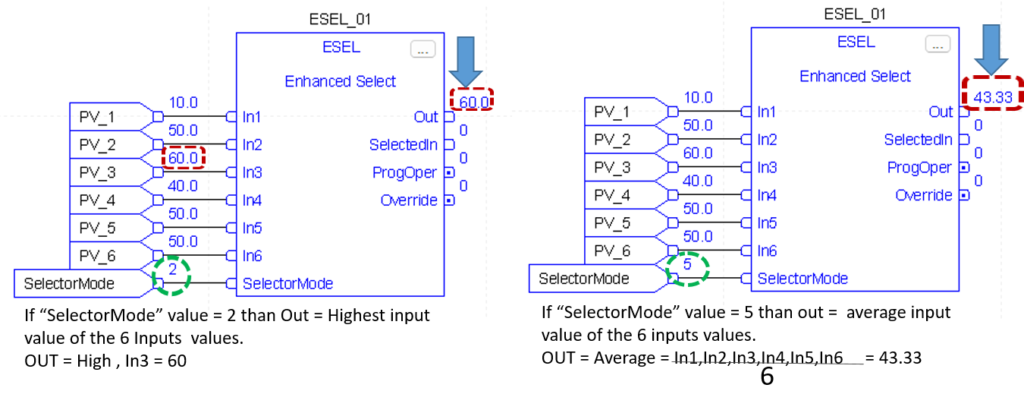
The ESEL instruction lets you select one of as many as six input. Selector options include :
- manual select (either by operator o by program)
- high select
- low select
- median select
- average (mean) select
Input Parameter
- In1
- In2
- In3
- In4
- In5
- In6
- Selector Mode
Description
- The first analog signal input to the instruction. Valid =any float Default =0.0
- The second analog signal input to the instruction. Valid = any float Default =0.0
- The third analog signal input to the instruction. Valid = any float Default = 0.0
- The fourth analog singnal input to the instruction. Valid = any float Default = 0.0
- The fifth analog signal input to the instruction. Valid = any float Default = 0.0
- The sixth analog signal input to the instruction. Valid = any float Default = 0.0
- Selector mode input. This value determines the action of the instruction.
Value Description
- manual
- high select
- low select
- median select
- average select
If this value is invalid, the instruction sets the appropriate bit in status and does not updete out. Valid = o to 4 Default =0
Output Parameter:
- Out
- SelectedIn
- ProgOper
- Override
Description:
- The calculated output of the algorithm. Arithmetic status flags are set for this output.
- Number of input selected. The instruction uses this value to display the number of the input currently being placed into the output. If the selector mode is average select, the instruction sets SelectedIn = 0.
- Program/Operator control indicator. Set when in Program control. Cleared when in Operator control.
- Override mode. Set when the instruction is in Override mode
Example
This ESEL instruction selects In1, In2, or In3,based on the SelectorMode. In this example, Selectormode = 1, Which means high select.The insturction determines which input value is the greatest and sets Out = greatest In

Selected Summer (SSUM)
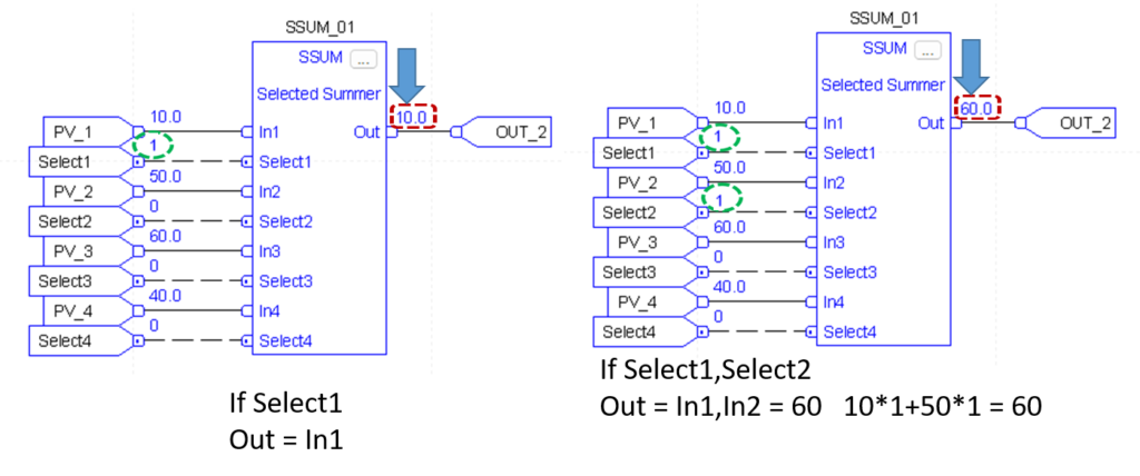
The SSUM instruction uses Boolean inputs to select real inputs to be algebraically summed.
Input Parameter
- In1
- Select1
- In2
- Select2
- In3
- Select3
- In4
- Select4
Description
- The first input to be summed. Valid = any float Default = 0.0
- Selector signal for the first input. Default is Cleared.
- The Second input to be summed. Valid = any float Default = 0.0
- Selector signal for the second input Default is cleared.
- The third input to be summed. Valid = any float Default = 0.0
- Selector signal for the third input. Default is cleared.
- The fourth input to be summed. Valid = any float Default = 0.0
- Selector signal for the fourth input. Default is cleared.
Output Parameter:
- Out
Description:
- The calculated output of the algorithm.Arithmetic status flags are set for this ouput.,
Example
The value of select 2 determine whether to select analogInput1 and analog_input2, respectively. The instruction then adds the selected inputs and places the result in Out.

Selectable Negate (SNEG)
The SNEG instruction uses a digital input to select between the input value and negative of the input value.
Input Parameter
- In
- NegateEnable
Description
- The analog signal input to the instruction. Valid = any float Default = 0.0
- Negate enable. When NegateEnable is set, the instruction sets Out to the negative value of In. Default is set.
Output Parameter:
- Out
Description:
- The calculated output of the algorithm.Arithmetic status flags are set for this ouput.,
Example
The output determines whether to negate In or not. The instruction sets out = In if NegateEnable is set. Out becomes an input parameter

Multiplexer (MUX)
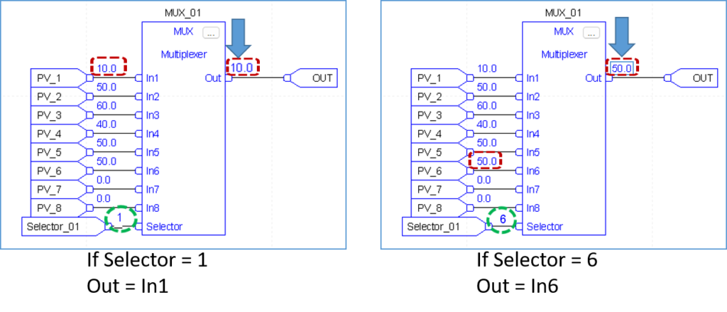
The MUX instruction selects one of eight inputs based on the selector input.
Input Parameter
- In1
- In2
- In3
- In4
- In5
- In6
- In7
- In8
- Selector
Description
- The first analog signal input to the instruction. Valid = any float Default = 0.0
- The second analog signal input to the instruction. Valid = any float Default = 0.0
- The third analog signal input to the instruction. Valid = any float Default = 0.0
- The fourth analog signal input to the instruction. Valid = any float Default = 0.0
- The fifth analog signal input to the instruction. Valid = any float Default = 0.0
- The sixth analog signal input to the instruction. Valid = any float Default = 0.0
- The seventh analog signal input to the instruction. Valid = any float Default = 0.0
- The eighth analog signal input to the instruction. Valid = any float Default = 0.0
- The selector input to the instruction. This input determines which of the inputs (1-8) is moved into Out. If this value is invalid (which includes 0), the instruction sets the appropriate bit in Status and holds Out at its current value. Valid = 1 to 8 Default = 0
Output Parameter:
- Out
Description:
- The selector output of the algorithm. Arithmetic status flags are set for this output.
Example
This MUX instruction selects In1, In2, In3, based on the Selector. The instruction sets Out = In which becomes an input an parameter for example , if value = 2, the instruction sets Out = analog _input2.

High / Low Limit (HLL)
The HLL instruction limits an analog input between two values. You can Select high/low,high,or low limits.
Input Parameter
- In1
Description
- The analog signal input to the instruction. Valid = any float Default = 0.0
Output Parameter:
- Out
- High Alarm
- Low Alarm
Description:
- The calculated output of the algorithm. Arithmetic status flags are set for this output.
- The high alarm indicator. Set when In >= HighLimit.
- The low alarm indicator. Set when In <= LowLimit
Example
This HLL instruction llimits In between two values and sets HighAlarm or LowAlarm, needed when In is outside the limits. The instruction sets Out = limited value of In, which becomes an input parameter for function_block_C.

Rate Limiter (RLIM)
The RLIM instruction limits the amount of change of a signal over time.
Input Parameter
- In1
- By Pass
Description
- The analog signal input to the instruction. Valid = any float Default = 0.0
- Request to bypass the algorithm.when set, Out = In. Default is cleared.
Output Parameter:
- Out
Description:
- The calculated output of the algorithm. Arithmetic status flags are set for this output.
Example
The RLIM instruction limit In by IncRate . If analog_input1 changes at a rate greater than the IncRate value, the instruction limits In. The instruction sets Out = rate limited value of In, which becomes an input parameter for function_block_C.

